
Two stage serial impingement cooling for isogrid structures

a technology of isogrid structure and impingement cooling, which is applied in the direction of machines/engines, liquid fuel engines, light and heating apparatus, etc., can solve the problems of affecting engine performance, affecting engine performance, and reducing engine efficiency, so as to keep the surface cooler, affect engine performance, and impart turbulence.

Inactive Publication Date: 2014-09-09
SIEMENS ENERGY INC
View PDF41 Cites 30 Cited by
  • Summary
  • Abstract
  • Description
  • Claims
  • Application Information

AI Technical Summary

Benefits of technology

[0003]Gas turbine engine components that are subjected to high temperatures are often actively cooled in order to maintain the metal temperature within acceptable limits. Components that partially define a path for the hot combustion gasses are often cooled using impingement cooling of the cooled side and / or film cooling of the hot side. Impingement cooling may be accomplished using a structure with impingement cooling holes designed to direct cooling air onto the cooled side of the component. Manufacturing limitations and design considerations constrain the design of impingement cooling holes. For example, the impingement cooling holes must be sized to permit small particles typically present in the cooling air to pass through without clogging the impingement cooling hole. Additionally, the advantageous effects impingement cooling provides are limited to a relatively small area adjacent the location of impingement. Consequently, many impingement cooling holes are required in order to effectively cool an entire area of the component. Cooling air used for impingement cooling is taken from the gas turbine engine compressor and is redirected away from the combustor to be used in the impingement cooling system. When air is redirected from combustion and used for any other purpose, the engine efficiency is reduced. As a result, increasing the number of impingement cooling holes decreases engine efficiency. Further, the minimum size of the impingement cooling holes required to avoid clogging of the holes often produces a flow volume of impingement cooling air that has a greater capacity to remove heat from the component than is necessary. In other words, a greater volume of cooling fluid may be delivered to the surface to be cooled than is actually required to sufficiently cool the surface. This extra volume of air may not be fully utilized, yet has been taken from the combustor. As a result the combustor operates at reduced efficiency.
[0004]Often impingement cooling air is then utilized to provide film cooling on the hot surface of the component via a film cooling hole that delivers the post impingement cooling air to the hot gas path. This film of post-impingement cooling air separates the surface of the component from the hot combustion gasses, and this helps to keep the surface cooler. However, film cooling air may also negatively impact engine performance by slowing the flow of the combustion gasses and by imparting turbulence to the flow (e.g. mixing losses). Any extra volume of cooling fluid in excess of the minimum necessary to sufficiently cool the surface further increases the negative impacts of film cooling on engine performance.
[0005]These problems are exacerbated in certain gas turbine engine designs where the combustion gasses are accelerated to approximately mach 0.8 as they exit the combustor, as opposed to conventional designs where this happens upon entering the first stage of the turbine. In such designs, a static pressure difference across the wall of the component that defines the hot gas path is greater than in conventional designs because the hot combustion gasses inside the component are moving much faster. This increased static pressure difference forces more cooling air through the impingement cooling holes than in the conventional design. Further, the greater static pressure difference increases the mixing losses, further reducing engine efficiency. Therefore, there exists a need in the art for improved cooling of components exposed to high operating temperatures.

Problems solved by technology

Manufacturing limitations and design considerations constrain the design of impingement cooling holes.
Additionally, the advantageous effects impingement cooling provides are limited to a relatively small area adjacent the location of impingement.
As a result, increasing the number of impingement cooling holes decreases engine efficiency.
This extra volume of air may not be fully utilized, yet has been taken from the combustor.
As a result the combustor operates at reduced efficiency.
However, film cooling air may also negatively impact engine performance by slowing the flow of the combustion gasses and by imparting turbulence to the flow (e.g. mixing losses).
Any extra volume of cooling fluid in excess of the minimum necessary to sufficiently cool the surface further increases the negative impacts of film cooling on engine performance.
These problems are exacerbated in certain gas turbine engine designs where the combustion gasses are accelerated to approximately mach 0.8 as they exit the combustor, as opposed to conventional designs where this happens upon entering the first stage of the turbine.
Further, the greater static pressure difference increases the mixing losses, further reducing engine efficiency.

Method used


Image

  • Two stage serial impingement cooling for isogrid structures
  • Two stage serial impingement cooling for isogrid structures
  • Two stage serial impingement cooling for isogrid structures

Examples


Embodiment Construction

[0013]An improved cooling system for components exposed to extreme high temperatures is disclosed herein. Such a component may be a component of an internal combustion engine, including a gas turbine engine. Various designs of such components may have pockets on the relatively cool side. These pockets may be there for structural strength or may be the result of other design considerations. An example, not meant to be limiting, of such a component is an advanced transition system that directs combustion gasses from a combustor to a first row of turbine blades. One such design is described in U.S. Pat. No. 7,721,547. In this design combustion gasses are accelerated from the end of the combustor to approximately 0.8 mach. The increased speed of the combustion gasses within the duct creates a larger static pressure difference between outside the component and inside the component than exists in conventional transition designs where the combustion gasses are moving much slower. The advan...


PUM


Abstract

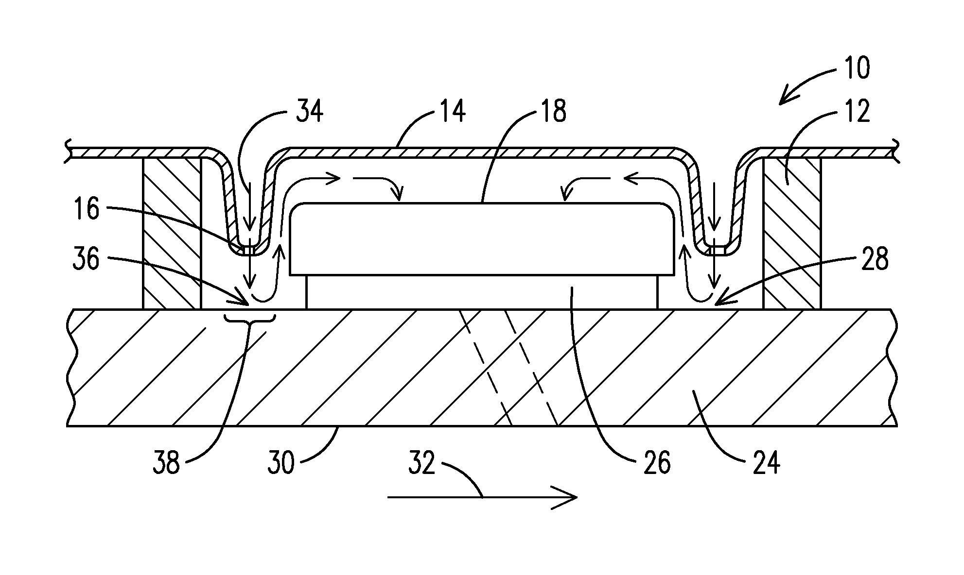
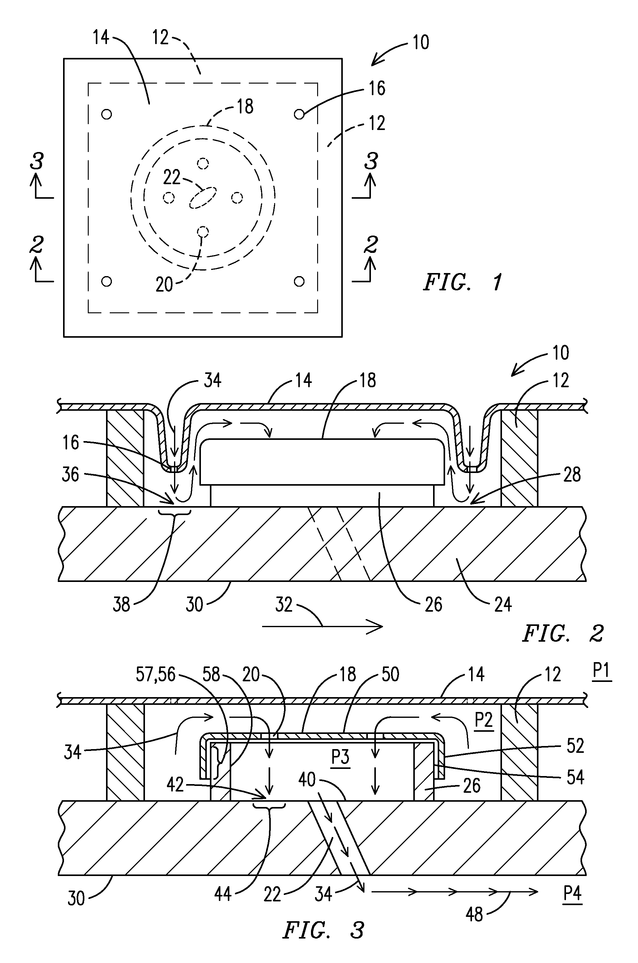
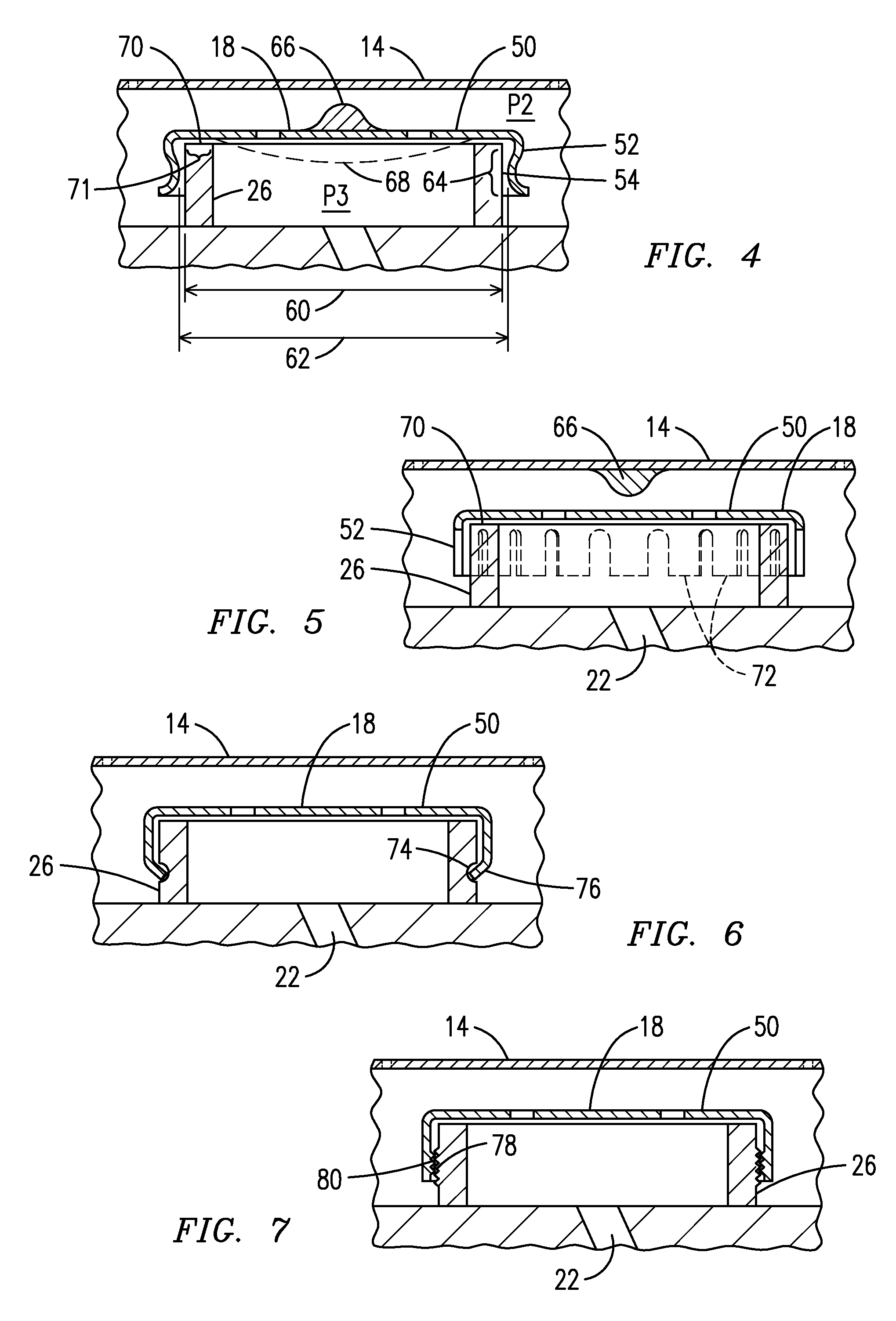
A system for cooling a wall (24) of a component having an outer surface with raised ribs (12) defining a structural pocket (10), including: an inner wall (26) within the structural pocket and separating the wall outer surface within the pocket into a first region (28) outside of the inner wall and a second region (40) enclosed by the inner wall; a plate (14) disposed atop the raised ribs and enclosing the structural pocket, the plate having a plate impingement hole (16) to direct cooling air onto an impingement cooled area (38) of the first region; a cap having a skirt (50) in contact with the inner wall, the cap having a cap impingement hole (20) configured to direct the cooling air onto an impingement cooled area (44) of the second region, and; a film cooling hole (22) formed through the wall in the second region.

Description

STATEMENT REGARDING FEDERALLY SPONSORED DEVELOPMENT[0001]Development for this invention was supported in part by Contract No. DE-FC26-05NT42644, awarded by the United States Department of Energy. Accordingly, the United States Government may have certain rights in this invention.FIELD OF THE INVENTION[0002]This invention relates to staged impingement cooling of a wall of a component. More particularly, this invention relates to staged cooling of an outer surface of the wall when the outer surface forms discrete pockets.BACKGROUND OF THE INVENTION[0003]Gas turbine engine components that are subjected to high temperatures are often actively cooled in order to maintain the metal temperature within acceptable limits. Components that partially define a path for the hot combustion gasses are often cooled using impingement cooling of the cooled side and / or film cooling of the hot side. Impingement cooling may be accomplished using a structure with impingement cooling holes designed to dire...

Claims


Application Information

Patent Timeline
Patent Type & Authority Patents(United States)
IPC IPC(8): H01L23/46F23R3/06F01D5/18F01D9/02F01D25/12
CPCF01D5/186F01D9/023F01D25/12F05D2260/202Y10S165/908F05D2260/201F23R3/002F23R3/007F23R3/06F23R2900/00017F23R2900/03042F23R2900/03044
Inventor LEE, CHING-PANGMORRISON, JAY A.
Owner SIEMENS ENERGY INC
Learn More