Manipulator with manual hold and comfortable articulation

a manipulator and manual hold technology, applied in the field of manipulators, can solve the problems of unsatisfactory decoupling, unsatisfactory actuation of the tool, and precise operations in which the movements to be carried out are complex,

Active Publication Date: 2014-09-02
DEXTERITE SURGICAL
View PDF14 Cites 0 Cited by
  • Summary
  • Abstract
  • Description
  • Claims
  • Application Information

AI Technical Summary

Benefits of technology

[0024]The problem addressed by the present invention is further improving the accuracy of the positioning and the driving in movement of a tool by a portable manipulator, avoiding all unwanted movements and ensuring good dissociation between positioning the tool and commanding movements of the tool during a surgical operation.
[0025]At the same time, the aim is to facilitate axial rotation of the manipulator about the longitudinal axis of the connecting arm by maneuvering the handle alone, limiting the amplitude of the necessary movements of the wrist, elbow and shoulder of the operator.

Problems solved by technology

These are delicate, precise operations in which the movements to be carried out are complex.
In the device of the above prior art document, loading the articulated lever necessarily produces simultaneous loading of the handle, with the result that there is no perfect decoupling between the movement of closing or opening the tool by the rotation of the lever and the positioning of the tool at the end of the connecting arm.
Moreover, when the handle has been pivoted, for improved operator comfort, pulling or pushing the handle to produce an axial movement of the manipulator is eccentric relative to the axis of the connecting arm, which necessarily produces a torque tending to incline the manipulator and unwanted movement of the tool, which the operator must attempt to correct by applying a torque to the handle.
Furthermore, in the pivoted position of the handle, pulling the handle to produce an axial movement of the manipulator necessarily produces unwanted loading of the lever and thus unwanted actuation of the tool.
However, it is found that there remain unwanted forces in planes non-perpendicular to the first articulation axis, with the result that the accuracy of positioning and driving the tool is not yet sufficient.
Moreover, in the above document, movements of the handle relative to the control unit cause loading of the actuators that move the distal tool relative to the connecting arm.
The manipulator is not portable.

Method used


Image

  • Manipulator with manual hold and comfortable articulation
  • Manipulator with manual hold and comfortable articulation
  • Manipulator with manual hold and comfortable articulation

Examples


Embodiment Construction

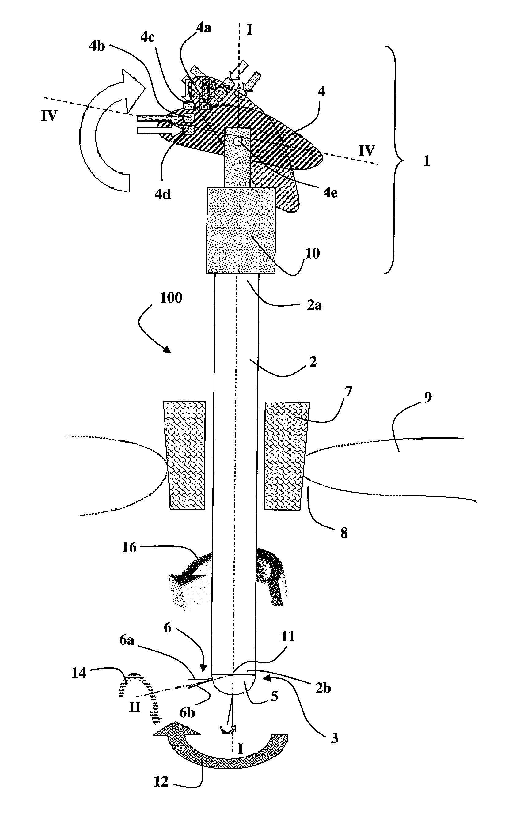
[0058]Consider firstly the general structure of a manipulator of the invention, as illustrated by the FIG. 1 embodiment.

[0059]In this embodiment, the manipulator 100 comprises a control unit 1, a connecting arm 2 that extends along a longitudinal axis I-I of the connecting arm, and a working unit 3.

[0060]The control unit 1 is mounted on the proximal end 2a of the connecting arm 2 and the working unit 3 is mounted on the distal end 2b of the connecting arm 2.

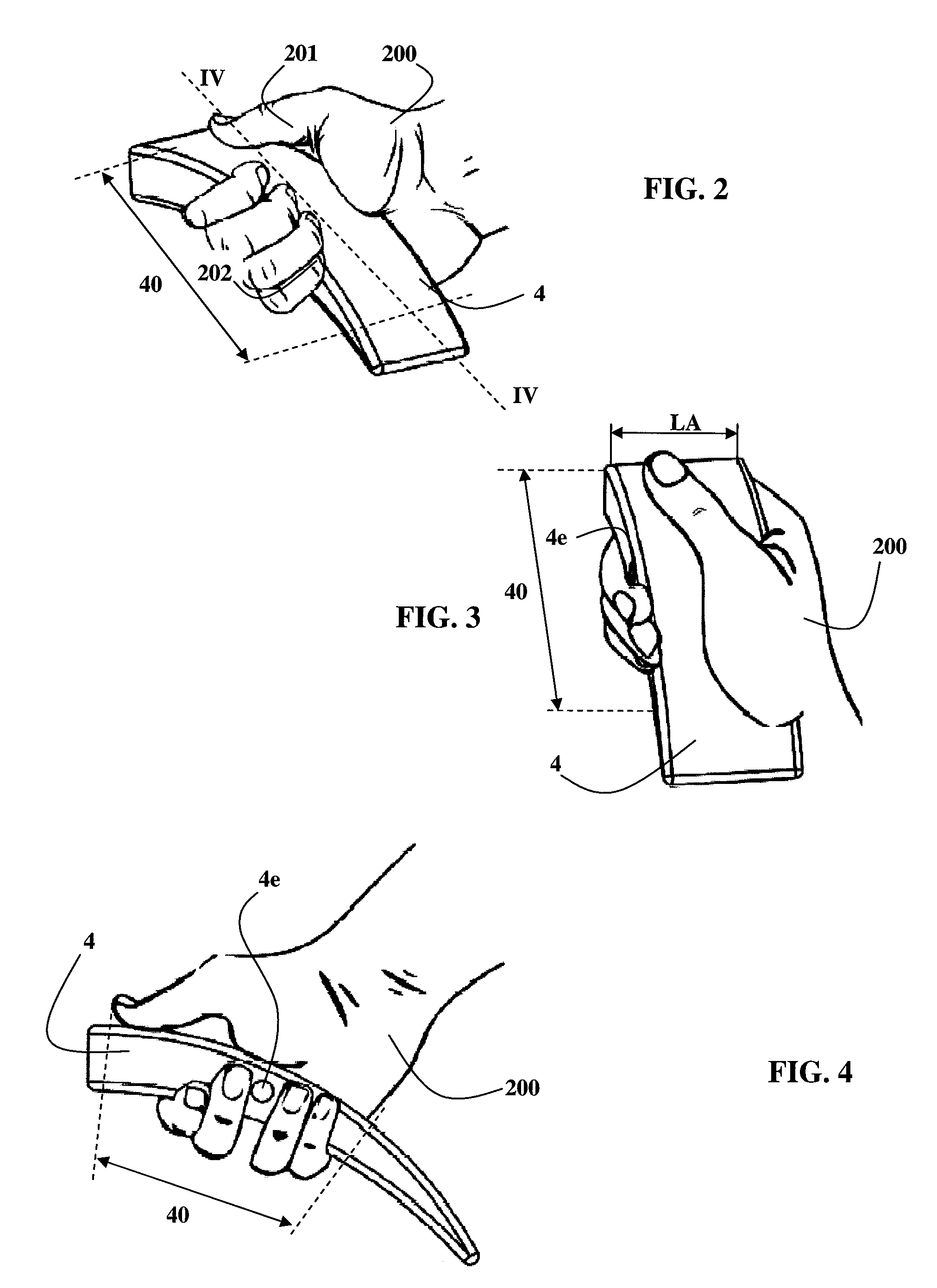
[0061]The control unit 1 comprises a handle 4 adapted to be held by one hand of an operator and a control body 10 containing various driving means for producing the appropriate movements in the working unit 3.

[0062]The control unit 1 is preferably balanced about the longitudinal axis I-I of the connecting arm, i.e. its center of gravity is substantially centered on said longitudinal axis I-I of the connecting arm.

[0063]The working unit 3 includes a tool support 5 adapted to support a tool 6. The figure shows by way of example a t...


PUM


Abstract

A manipulator includes a control unit (1), with handle (4) and control buttons (4a-4d), and a connecting arm (2) which, at its proximal end (2a), carries the control unit (1) and, at its distal end (2b), carries a work unit (3). The handle (4) is articulated about at least one transverse articulation axis (4e), which is itself situated at an intermediate position along the handle (4). A particularly ergonomic manipulator is thus obtained which is easy to learn to use and which efficiently separates the stresses arising from movements of the tool support (5) and the stresses arising from holding and moving the manipulator itself.

Description

TECHNICAL FIELD OF THE INVENTION[0001]The present invention concerns manipulator devices for controlling from outside an operating area the movements of a manipulation instrument situated inside the operating area.[0002]In particular, these manipulator devices are used to place and control a surgical tool in minimally invasive surgical applications employing endoscopy.[0003]In these applications, it is necessary to be able to move and to control a surgical tool to effect diverse operations such as a suture, tightening a knot, fine dissection of tissues. These are delicate, precise operations in which the movements to be carried out are complex.[0004]The invention concerns more specifically portable manipulator devices in which a surgical tool is placed at the end of a manipulator that the surgeon holds in one hand and essentially has a connecting arm with a proximal end and a distal end. The proximal end of the connecting arm includes a control unit having a handle adapted to be hel...

Claims


Application Information

Patent Timeline
Patent Type & Authority Patents(United States)
IPC IPC(8): A61B19/00A61B17/00A61B17/04A61B17/29
CPCA61B17/2909A61B19/22A61B17/0469A61B2017/2929A61B2019/2269A61B2017/0042A61B2017/291A61B34/70A61B34/74
Inventor BARRIER, PASCALOLLAGNIER, JEREMYROSSET-LANCHET, REMI
Owner DEXTERITE SURGICAL
Why Eureka
Try Eureka