
Device and method for minimally invasive spinal intervention

a spinal cord and endoscope technology, applied in the field of endoscope devices for minimally invasive spinal cord intervention, can solve the problems of inconvenient removal process, inability to remove bone tissue at the same time, and the tool has to have a very small diameter, so as to reduce the risk of nerve damage or nerve damage to tissue which should not be damaged or eliminated.

Active Publication Date: 2014-09-02
JOIMAX GMBH
View PDF29 Cites 71 Cited by
  • Summary
  • Abstract
  • Description
  • Claims
  • Application Information

AI Technical Summary

Benefits of technology

The invention is a cutting tool for use in human body that can be inserted without causing damage to tissue. It also allows for a clear view of the area to be cut from the inside out using an endoscope. The tool has a tapered shape that can be easily guided and can also include an anchoring tool to fix it in place in the spinal column. The tool has a connection configuration for non-rotating connection with a handle, and is designed to minimize damage to tissue and risk to nerves.

Problems solved by technology

However, the problem may arise that bone tissue or bony growths are present in the working area which hinder the cannula from advancing as far as into the region of the disc to be treated or which have a troublesome effect on the orientation of the cannula with regard to the working area.
However, the problem arises here that the tool has necessarily to have a very reduced diameter (maximum diameter 3.5 mm) and the process of removing bone tissue may take too much time, which is disadvantageous to the patient.
The difficulty here is that the user has to undertake the intervention without a direct view of the soft tissue present, with the attendant risk of injury to nerve tissue in spiral regions.

Method used


Image

  • Device and method for minimally invasive spinal intervention
  • Device and method for minimally invasive spinal intervention
  • Device and method for minimally invasive spinal intervention

Examples


Embodiment Construction

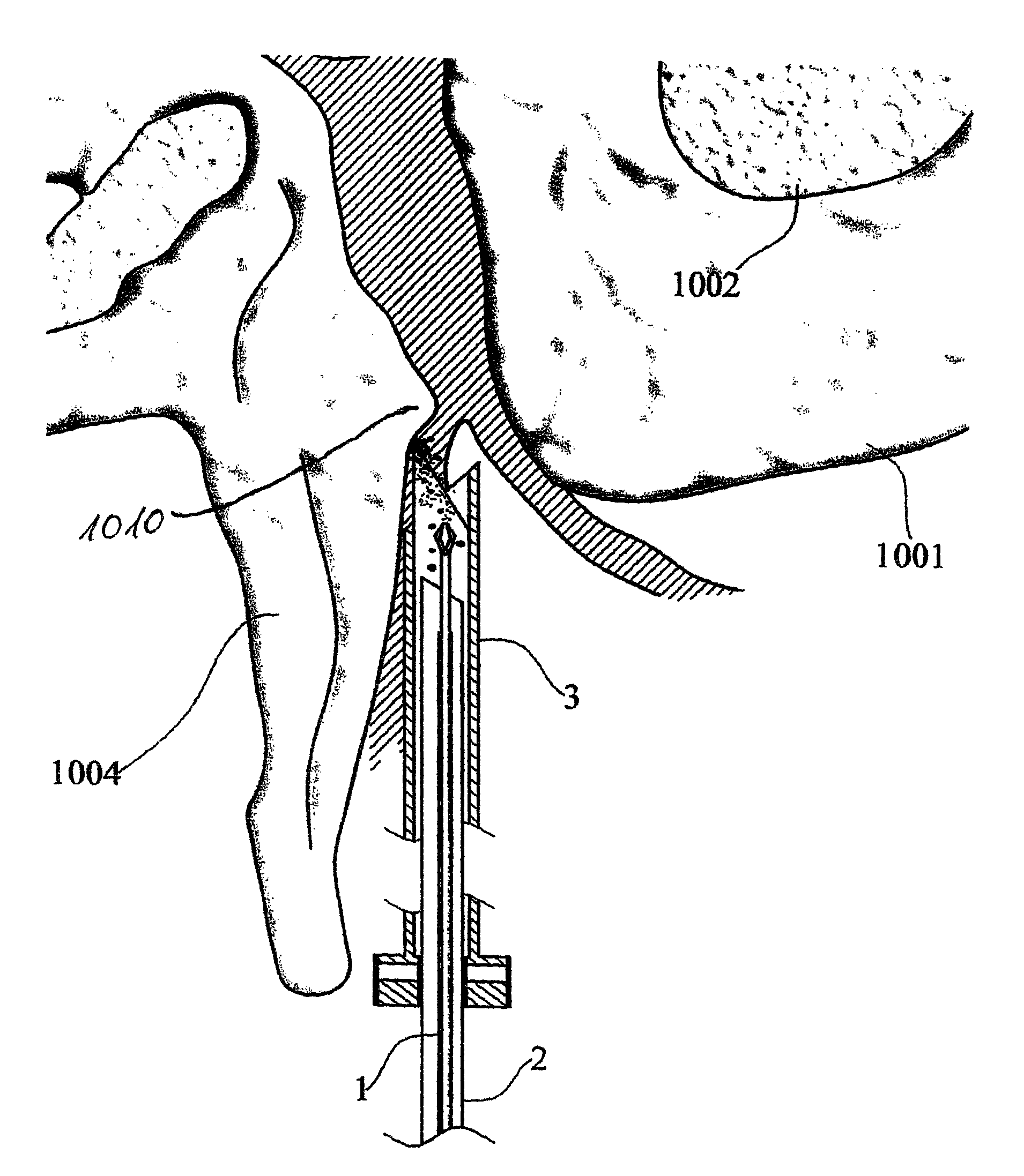
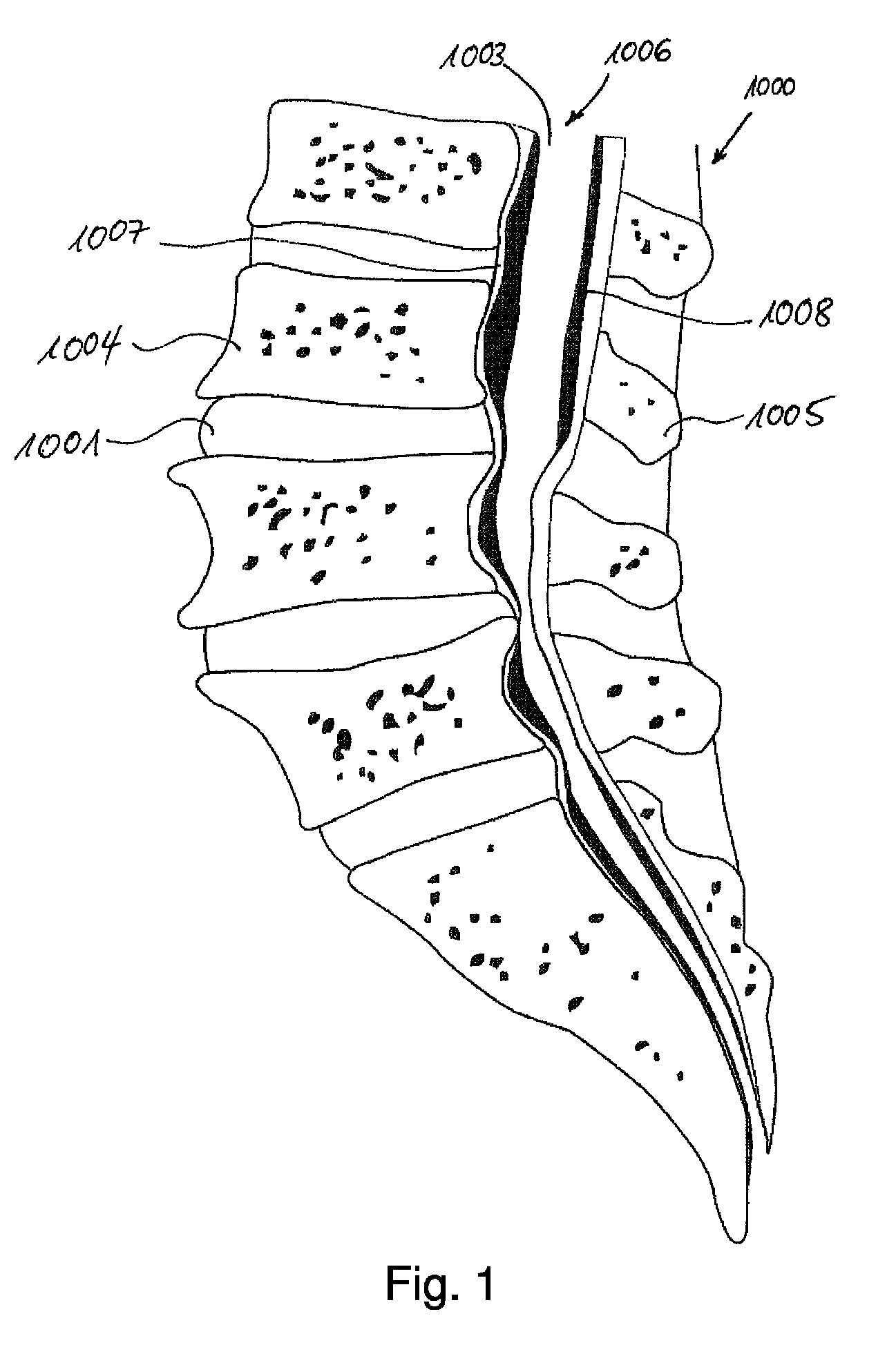
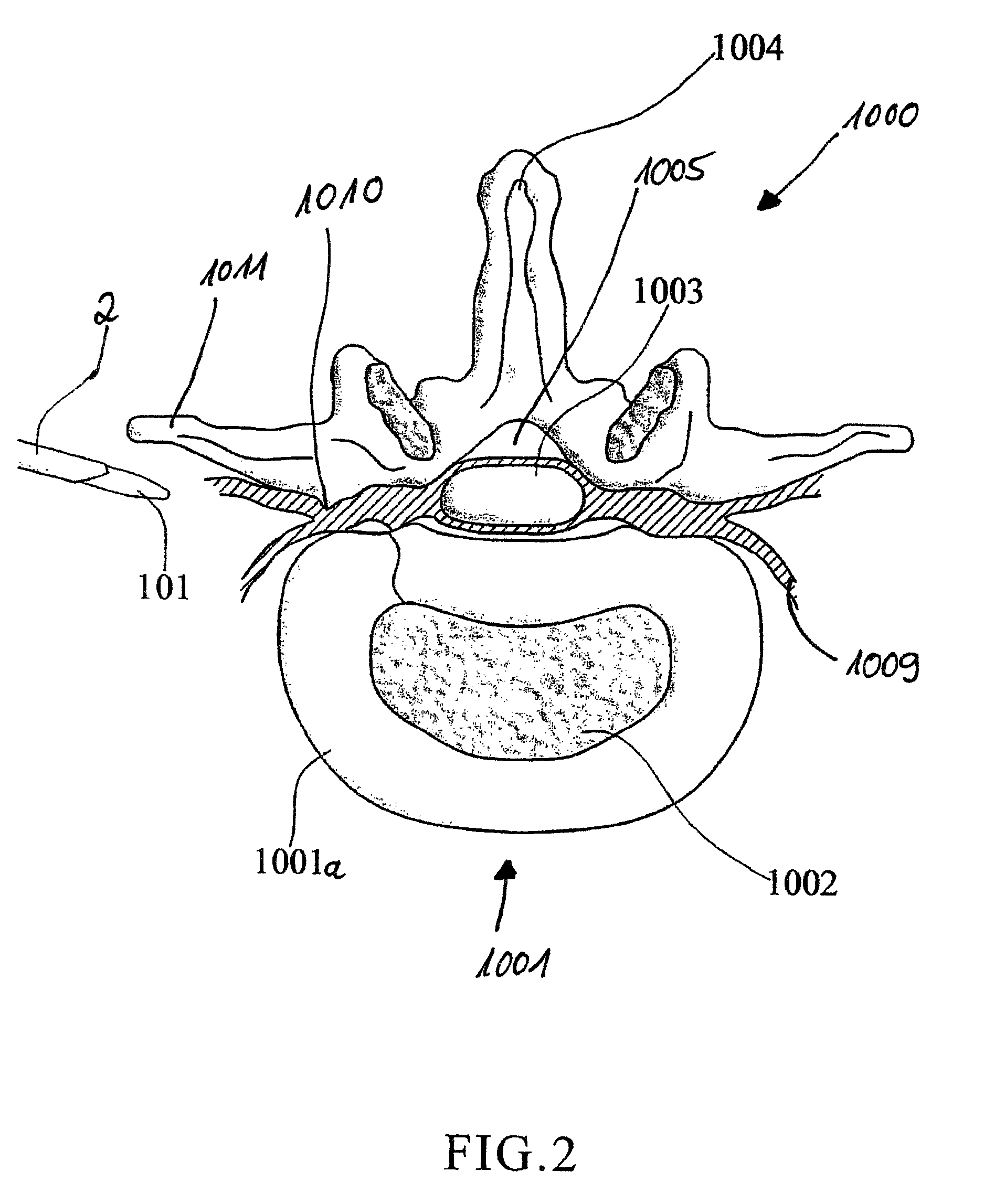
[0049]Referring to the drawings in particular, FIG. 1 shows in longitudinal section the lower area of a spinal column 1000 with vertebrae 1004 and the spinous process (Processus spinosus) 1005 extending backwards (dorsally) away therefrom, between which—in the cross-section shown—are located the vertebral holes (vertebral foramen) forming the spinal canal 1006 of the spinal column 1000. Between the vertebrae 1004 there are located the intervertebral discs 1001 with their nucleus 1002 (FIG. 2) and their ring (annulus) 1001a.

[0050]The vertebrae are connected together at the front (ventral) side of the spinal canal by the anterior longitudinal ligament 1007 (Ligamentum longitudinale anterius), while the posterior longitudinal ligament (Ligamentum longitudinale posterius) 1008 is located to the rear of the spinal canal 1006, in front of the spinous processes 1005, the posterior longitudinal ligament being connected only loosely to the vertebrae but firmly to the discs 1001. Nerve tissu...


PUM


Abstract

The invention proposes a device for minimally invasive intervention in the skeletal region, in particular on the spinal column, having at least a cannula with a distal end generally bevelled in shape relative to a symmetrical axis of the cutting tool and an optical probe (endoscope) for insertion through the cavity of the cannula. The device is further characterized in that the cannula takes the form of a hollow cutting tool, in which the most distal region of the distal end comprises a cutting edge, which is incorporated into the edge of the wall of the cutting tool.

Description

CROSS REFERENCE TO RELATED APPLICATIONS[0001]This application is a United States National Phase application of International Application PCT / EP2007 / 010238 and claims the benefit of priority under 35 U.S.C. §119 of Spanish Patent Application ES 2006 03026 / 4 filed Nov. 27, 2006, the entire contents of which are incorporated herein by reference.FIELD OF THE INVENTION[0002]The invention relates to a device for minimally invasive endoscopic intervention in the skeletal region, in particular on the spinal column, having the following elements: a cannula with a distal end having a generally bevelled shape relative to a symmetrical axis of the cutting tool, an optical probe (endoscope) for insertion through the cavity of the cannula; and to a method for minimally invasive intervention in the spinal region, having at least the following steps: at least one rod is brought percutaneously with its distal end at least as far as into the region of the intervention and a hollow tube with bevelled ...

Claims


Application Information

Patent Timeline
Patent Type & Authority Patents(United States)
IPC IPC(8): A61B17/16
CPCA61B17/1659A61B5/417A61B5/6848A61B17/1604A61B17/1637A61B17/1671A61B17/1735A61B17/1757A61B17/320016A61B17/3421A61B2017/00296A61B2017/00353A61B2017/00464A61B2019/5437A61B2090/3937A61B17/32002A61B17/16A61B17/17A61B1/313A61B17/70
Inventor MORGENSTERN LOPEZ, RUDOLFRIES, WOLFGANG
Owner JOIMAX GMBH
Learn More