Mobile diesel power system with separated engine and exhaust

a diesel power system and engine technology, applied in the field of locomotives, can solve the problems of high-cost diesel fuel, inability of railroads and locomotive manufacturers to manage, and financial challenges of the us railroad industry, so as to reduce fuel consumption, improve power, and ease the space constraints of the locomotiv

Inactive Publication Date: 2014-09-02
CLEAN ROLLING POWER
View PDF13 Cites 1 Cited by
  • Summary
  • Abstract
  • Description
  • Claims
  • Application Information

AI Technical Summary

Benefits of technology

[0011]Accordingly, the present disclosure may have one or more of the following advantages: a tender to house an exhaust after-treatment system thereby easing space constraints on the locomotive power traction car. Additionally, said tender may include a large fuel tank, waste heat recovery system, and energy storage, thereby providing the means to substantially decrease fuel consumption or increase power, both with the option of switching to a different fuel source.
[0012]In another embodiment, the present disclosure comprises a tender to house an engine cooling system thereby easing space constraints on the locomotive power traction car. Additionally, said tender may include a fuel tank, exhaust after-treatment system, and energy storage, thereby additionally providing the means to substantially decrease fuel consumption or increase power, both with the option of switching to a different fuel source.
[0013]In another embodiment, the present disclosure comprises a tender to house a waste heat recovery system thereby easing space constraints on the locomotive power traction car. Additionally, said tender may include a large fuel tank, exhaust after-treatment system, and energy storage, thereby additionally providing the means to substantially decrease fuel consumption or increase power, both with the option of switching to a different fuel source.
[0014]Migrating the railroad away from petroleum based fuels to compressed natural gas or dimethly ether (DME) not only helps reduce all emissions including CO2, but it also reduces the railroad industry's vulnerability to the volatility of the international petroleum market. One challenge for migrating to these fuels is the increased size of the fuel storage tanks. DME requires twice the volume as diesel fuel and CNG requires even more space. With a tender, the space for such tanks is available.
[0015]The railroad industry is very sensitive to locomotive fuel economy due to the large amount of fuel used by the industry as this cost represents the largest single operating expense for the railroads. Thus, methods which can improve performance by fractional percentages is looked upon favorably. As with most internal combustion engines, those on a locomotive expel up to 60% of the heat energy in the fuel burned as wasted heat. With the use of a waste heat recovery system, which is too physically large to fit within an existing locomotive but can be easily fitted within a tender, a fuel savings of 10% or greater is possible.

Problems solved by technology

Impending circumstances will financially challenge the US railroad industry.
Specifically, the continued reliance on high-cost diesel fuel and the implementation of stricter emission controls are conditions that the railroads and locomotive manufacturers are currently ill-equipped to manage with current system architecture.
Railroads are significant contributors to air pollution.
In addition to pollution concerns from NOx and PM, CO2 emissions are also coming under increased scrutiny.
These impacts include an increase in the cost of transporting goods (which, in turn, leads to increases in retail prices, i.e., inflation), increased global tensions (as a large fraction of known oil reserves are located in tumultuous regions of the globe), and increased cost of power generating systems, including vehicles, (due to the need to add ever more complex, and costly, exhaust treatment systems).

Method used


Image

  • Mobile diesel power system with separated engine and exhaust
  • Mobile diesel power system with separated engine and exhaust
  • Mobile diesel power system with separated engine and exhaust

Examples


Embodiment Construction

[0030]To facilitate an understanding of the present disclosure, a number of terms and phrases are defined below:

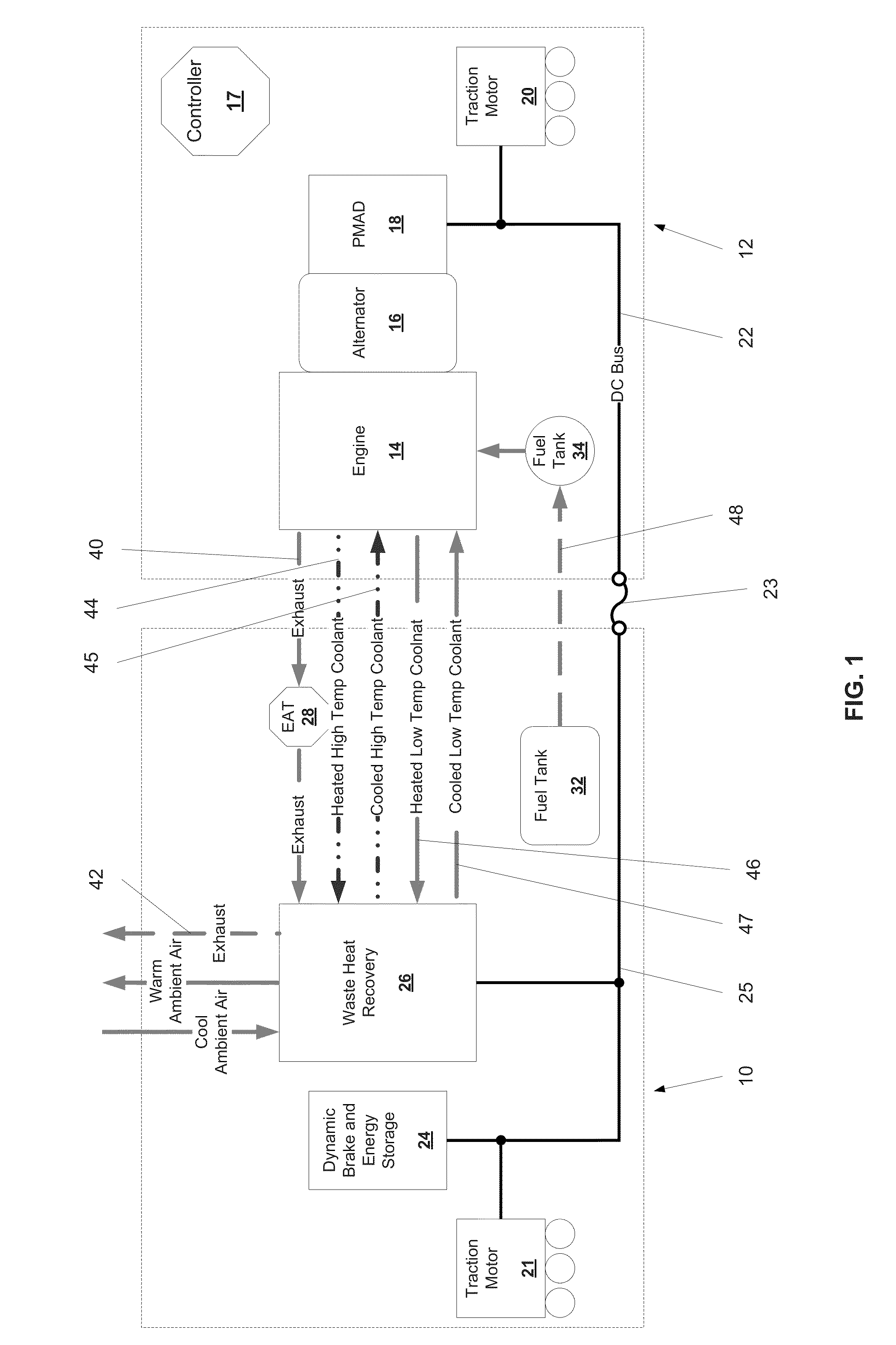
[0031]Alternator: An electromechanical device used to convert mechanical power to alternating current electrical power. In the context of this disclosure, the term alternator can apply to actual alternators, generators, or any other electromechanical device typically used to convert mechanical power into electrical power.

[0032]Dimethyl ether (DME): DME is an organic compound with the formula CH3OCH3. The simplest ether, it is a colorless gas that is a useful precursor to other organic compounds and an aerosol propellant. It has similar storage characteristics as propane (LPG) except it is a liquid at lower pressures and therefore can use a thinner and lighter pressure vessel. Dimethyl ether is also promising as a clean-burning hydrocarbon fuel. DME is an especially promising fuel in diesel engines, owing to its high cetane number, 55, which is greater than that of diesel, ...


PUM


Abstract

According to the present disclosure, a train comprising one or more locomotives coupled to one or more tenders, which contain at least one of an exhaust after-treatment or a waste heat recovery system and optionally one or more other locomotive subsystems, such as dynamic braking, energy storage, driven wheels, and fuel storage, is provided. Accordingly, the present disclosure may have one or more of the following advantages: a tender to house an exhaust after-treatment system thereby easing space constraints on the locomotive power traction car. Additionally, said tender may include a large fuel tank, waste heat recovery system, and energy storage, thereby providing the means to substantially decrease fuel consumption or increase power, both with the option of switching to a different fuel source.

Description

CROSS-REFERENCE TO RELATED APPLICATIONS[0001]This application claims the benefit of U.S. Provisional Application No. 61 / 244,551, filed Sep. 22, 2009 which is incorporated herein by reference in its entirety.BACKGROUND OF THE INVENTION[0002]The present disclosure relates to locomotives, specifically the use of an equipped tender which serves to decrease fuel consumption or increase power and control emissions of one or two attached locomotives.[0003]Impending circumstances will financially challenge the US railroad industry. Specifically, the continued reliance on high-cost diesel fuel and the implementation of stricter emission controls are conditions that the railroads and locomotive manufacturers are currently ill-equipped to manage with current system architecture.[0004]Transportation by rail forms the basis for inter-city freight in the US, holding more than 40% of this market. One of the reasons for this is that rail transport is more fuel efficient and less expensive than othe...

Claims


Application Information

Patent Timeline
Patent Type & Authority Patents(United States)
IPC IPC(8): F01N3/02
CPCY02T10/166Y02T10/16F02G5/02F01N5/02F02G5/04F02G2260/00B61C17/02Y02T30/10Y02T10/12Y02T30/00
Inventor COOK, DAVID
Owner CLEAN ROLLING POWER
Why Eureka
Try Eureka