Fixing device using heating scheme for image forming apparatus

a technology of fixing device and heating scheme, which is applied in the direction of electrographic process apparatus, instruments, optics, etc., can solve the problems of inability to calculate power suppliability to the other heater, easy overheating of components, and inability to fix parts at the same time. , to achieve the effect of suppressing the increase in the time of rise of the fixing devi

Active Publication Date: 2014-08-26
CANON KK
View PDF11 Cites 6 Cited by
  • Summary
  • Abstract
  • Description
  • Claims
  • Application Information

AI Technical Summary

Benefits of technology

[0009]The present invention has been made in consideration of the above-described problems, and has as its feature, to provide a fixing device that includes a safety circuit for partially limiting driving of heating elements during stopping of rotation of a rotation member and can set the upper limit of a power suppliable to each of a plurality of heating elements while suppressing an increase in the time of rise of the fixing device to a fixing enable state.

Problems solved by technology

Especially, when the pressure roller stops rotating, heat generated by the heater escapes to only part of the pressure roller, and the components are readily overheated.
In a device including the safety circuit described in Japanese Patent Laid-Open No. 2008-275900, driving of heating elements is partially limited due to the action of the safety circuit (for example, only one of two heaters generates heat) in the preheat stage, that is, in the stage before the start of rotation (rotation stop stage).
Hence, the power suppliable to the other heater cannot be calculated.

Method used


Image

  • Fixing device using heating scheme for image forming apparatus
  • Fixing device using heating scheme for image forming apparatus
  • Fixing device using heating scheme for image forming apparatus

Examples


first embodiment

(1) Image Forming Apparatus

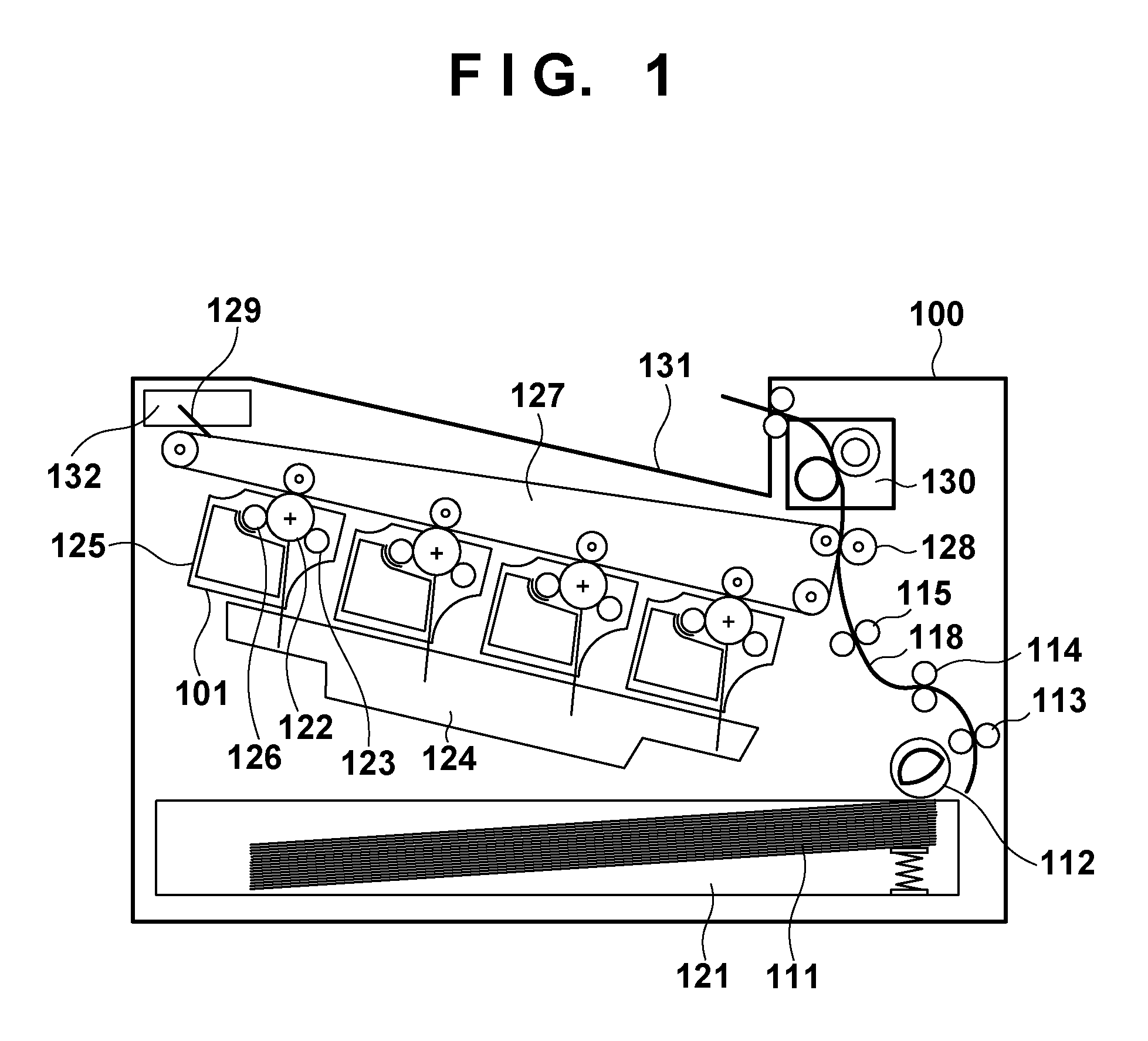
[0026]FIG. 1 illustrates the schematic arrangement of an image forming apparatus according to the embodiment of the present invention. An image forming apparatus 100 forms a multicolor image by overlaying four color toner images of yellow, cyan, magenta, and black using electrophotography. The image forming apparatus 100 includes four stations corresponding to yellow (Y), magenta (M), cyan (C), and black (K). The stations have a common arrangement. Hence, one station will be explained.

[0027]An all-in-one cartridge 101 is formed by integrating a photosensitive drum 122 serving as an image carrier, a charging roller 123 serving as a charger, a developing roller 126 serving as a developer, and the like. The charging roller 123 uniformly charges the surface of the photosensitive drum 122. A scanner unit 124 irradiates the photosensitive drum 122 with exposure light corresponding to image information so as to form an electrostatic latent image on the photosensi...

second embodiment

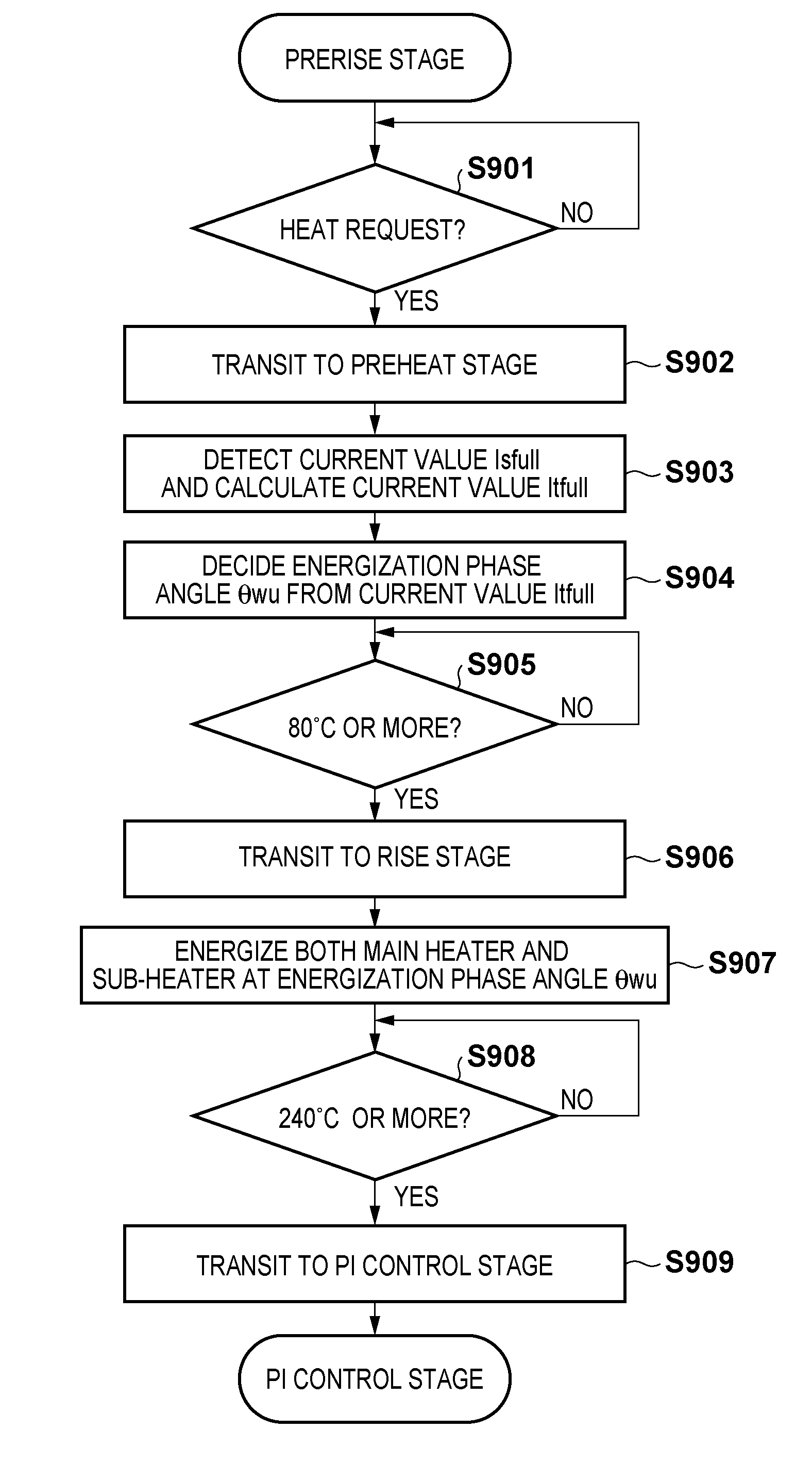
[0075]The first and second embodiments have a common basic arrangement, and only different portions will be described. Since sections (1), (2), (4), and (5) are common, sections (3), (6), and (7) will be explained here. In particular, in the second embodiment, a sub-heater that is one of a plurality of heat generation unit constituting a heater 205 and a main heater that comprises the remaining heat generation units are alternately energized in the preheat stage.

(3′) Ceramic Heater

[0076]FIG. 11 shows the arrangement of the heater 205 and the heat generation distribution of the heater 205. A main heater 1202a and a sub-heater 1202b have the same arrangements as those of the above-described main heater 302a and the sub-heater 302b but different heat generation distributions, as shown in FIG. 11. In the main heater 1202a, the heat generation amount is large at the center of the heating element. However, in the sub-heater 1202b, the heat generation amount is large at the ends of the hea...


PUM


Abstract

When a rotation member stops rotation, driving of a plurality of heating elements is sometimes partially limited. A control unit detects a current flowing to the plurality of heating elements when the rotation member stops rotation, and driving of the plurality of heating elements is partially limited. The control unit sets the power ratio of power to be supplied to the plurality of heating elements during a period in which the rotation member rotates to raise a fixing device to a fixing enable state in accordance with the detection result.

Description

BACKGROUND OF THE INVENTION[0001]1. Field of the Invention[0002]The present invention relates to a fixing device using a heating scheme for an image forming apparatus.[0003]2. Description of the Related Art[0004]Currently, a heat roller scheme using a halogen heater as a heat source or a film heating scheme using a ceramic heater as a heat source is widely used for a fixing device used in an image forming apparatus. Such a fixing device needs a protection mechanism for suppressing damage to components arranged around the pressure roller in the case of overheating.[0005]Especially, when the pressure roller stops rotating, heat generated by the heater escapes to only part of the pressure roller, and the components are readily overheated. To prevent this, Japanese Patent Laid-Open No. 2008-275900 describes providing a rotation detection circuit for detecting rotation of a pressure roller and a hardware safety circuit for limiting and partially driving of heating elements during rotatio...

Claims


Application Information

Patent Timeline
Patent Type & Authority Patents(United States)
IPC IPC(8): G03G15/20
CPCG03G15/205G03G15/2082G03G15/2042G03G2215/2035
Inventor ASANO, HIROKI
Owner CANON KK
Why Eureka
Try Eureka