
Liquid crystal display with UV or blue light blocking filter

a technology of liquid crystal display and filter, applied in non-linear optics, instruments, optics, etc., can solve problems such as degradation of liquid crystal display cells, and achieve the effect of improving efficiency, reducing or substantially preventing cross talk

Active Publication Date: 2014-08-26
SAMSUNG DISPLAY CO LTD
View PDF24 Cites 13 Cited by
  • Summary
  • Abstract
  • Description
  • Claims
  • Application Information

AI Technical Summary

Benefits of technology

[0009]The disclosed liquid crystal display improves efficiency and reduces or substantially prevents cross talk in a self-emission liquid crystal display.
[0028]According to an exemplary embodiment, the red, green and blue phosphors are used to form emission layers such that a light efficiency is improved, and a polarizer is disposed in the liquid crystal display cell, thereby improving a cross talk.

Problems solved by technology

A self-emission liquid crystal display can use an ultraviolet backlight to provide high light efficiency, however, while not wanting to be bound by theory, it is believed that ultraviolet (“UV”) light can cause degradation of a liquid crystal display cell.

Method used


Image

  • Liquid crystal display with UV or blue light blocking filter
  • Liquid crystal display with UV or blue light blocking filter
  • Liquid crystal display with UV or blue light blocking filter

Examples


Embodiment Construction

[0036]Aspects, advantages, and features of the present invention and methods of accomplishing the same may be understood more readily by reference to the following detailed description of preferred embodiments and the accompanying drawings. The present invention may, however, may be embodied in many different forms, and should not be construed as being limited to the embodiments set forth herein. Rather, these embodiments are provided so that this disclosure will be thorough and complete and will fully convey the concept of the invention to those skilled in the art, and the present invention will only be defined by the appended claims.

[0037]The present invention is described more fully hereinafter with reference to the accompanying drawings, in which exemplary embodiments of the invention are shown. As those skilled in the art would realize, the described embodiments may be modified in various different ways, all without departing from the spirit or scope of the present invention.

[0...


PUM

PropertyMeasurementUnit
thicknessaaaaaaaaaa
thicknessaaaaaaaaaa
thicknessaaaaaaaaaa

Abstract

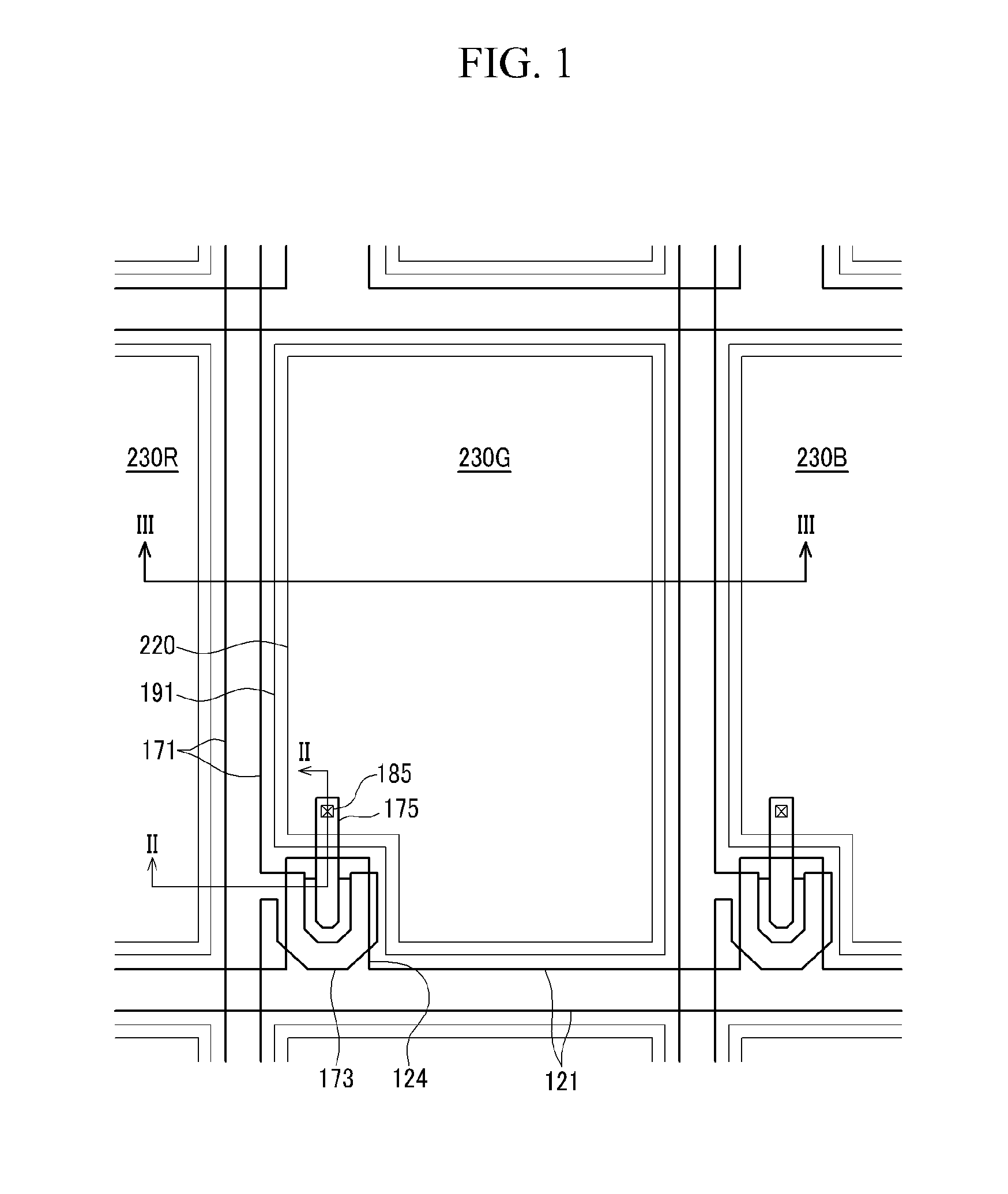
A liquid crystal display including a first substrate; a light-blocking member disposed on the first substrate; an emission layer disposed on the first substrate; an ultraviolet-light blocking filter disposed on the emission layer; a lower polarizer disposed on the ultraviolet-light blocking filter; a gate line and a data line disposed on the lower polarizer and substantially perpendicular to each other; a thin film transistor electrically connected to the gate line and the data line; a pixel electrode electrically connected to the thin film transistor; a second substrate disposed facing the first substrate; a common electrode disposed on the second substrate; and a liquid crystal layer interposed between the first substrate and the second substrate.

Description

[0001]This application claims priority to Korean Patent Application No. 10-2008-0100139, filed on Oct. 13, 2008, and all the benefits accruing therefrom under 35 U.S.C. §119, the contents of which in its entirety are herein incorporated by reference.BACKGROUND OF THE INVENTION[0002](a) Field of the Invention[0003]This disclosure relates to a liquid crystal display.[0004](b) Description of the Related Art[0005]A liquid crystal display (“LCD”) is a type of flat panel display. An LCD includes two substrates with electrodes disposed thereon and a liquid crystal layer interposed between the two substrates. In the LCD, a voltage is applied to the electrodes to realign liquid crystal molecules of the liquid crystal layer to thereby regulate transmittance of light passing through the liquid crystal layer.[0006]A type of LCD is an LCD wherein field-generating electrodes are respectively disposed on two display panels. The two display panels can include a thin film transistor array panel and ...

Claims


Application Information

Patent Timeline
Patent Type & Authority Patents(United States)
IPC IPC(8): G02F1/1335G02F1/1333
CPCG02F1/133617G02F1/133512G02F1/133603G02F1/136209G02F2001/136222G02F2201/086G02F1/136222G02F1/1335
Inventor RHO, SOON-JOONLEE, HYEOK-JINLEE, HEE-KEUNJEON, BAEK-KYUN
Owner SAMSUNG DISPLAY CO LTD
Learn More