
Respiratory secretion retention device, system and method

a retention device and respiratory secretion technology, applied in the field of respiratory secretions and airway devices, can solve the problems of imposing unnecessary and excessive dead space, affecting the adherence of respiratory secretions, and forcing egress through the lumen, so as to reduce the adhesion of respiratory secretions

Inactive Publication Date: 2014-08-26
MERGENET MEDICAL
View PDF3 Cites 3 Cited by
  • Summary
  • Abstract
  • Description
  • Claims
  • Application Information

AI Technical Summary

Benefits of technology

The invention is a device that helps to remove respiratory secretions from a patient with respiratory illnesses. It includes an airway conduit that has a section where the flow of gases and respiratory secretions slows down, allowing material with greater mass to separate out. The device also has a partial barrier or gas flow diverter that causes the respiratory secretions to impact the surface of the barrier or diverter and be separated from the gas flow. The airway conduit can be connected to a suction device for automatic or continuous removal of respiratory secretions. The invention also includes a connector for the respiratory gas delivery conduit that decreases dead air space and ensures expiratory gas flow goes through the device while inspiratory flow enters from the patient end. These technical features improve the effectiveness of the device in removing respiratory secretions and promoting patient respiratory wellness.

Problems solved by technology

Second, most artificial airways will have an inflatable cuff near the distal end of the tube.
One of the common issues with having the patient breathe through these artificial airways is that respiratory secretions, which would normally enter the pharynx and get swallowed, expectorated or coughed out through the mouth, are forced to egress through the lumen of the artificial airway.
Such fluid trap devices are disadvantageous as they impose unnecessary and excessive dead-space (e.g., exhaled air that is re-breathed) to achieve the independent orientation.

Method used


Image

  • Respiratory secretion retention device, system and method
  • Respiratory secretion retention device, system and method
  • Respiratory secretion retention device, system and method

Examples


Embodiment Construction

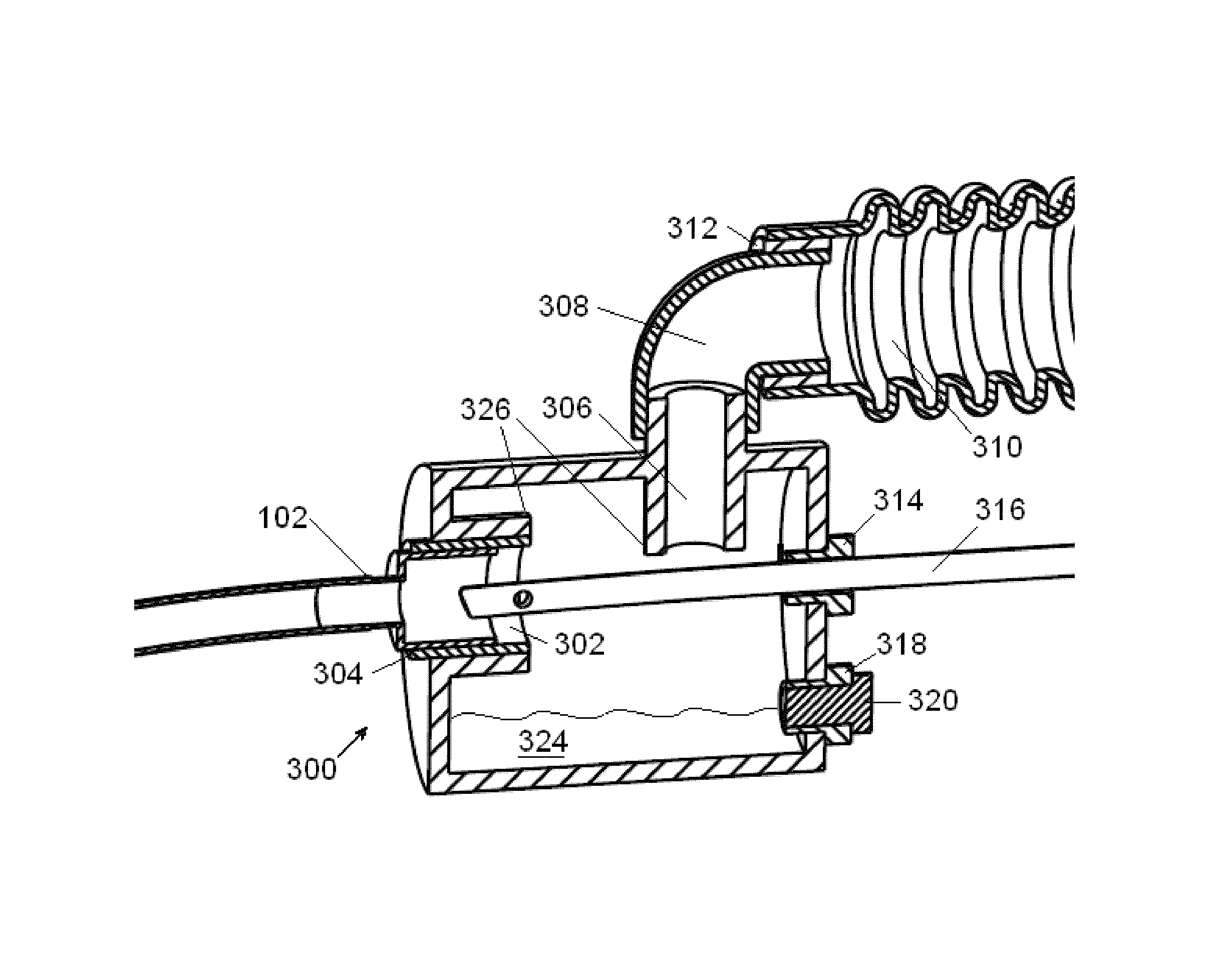
[0053]During the exhalation phase of respiration fluid is expelled from the lower respiratory tract. Most of the fluid are in the form of gases, but liquid and particulate matter are also expelled. The RSR acts to separate the “respiratory secretions” and “airway fluids” from the respiratory gasses. For purposes of this disclosure, “respiratory secretions” and “airway fluids” may include sputum, mucus, mucus plugs, and / or other all other nongaseous matter which may be conveyed out of the lower respiratory tract and the like.

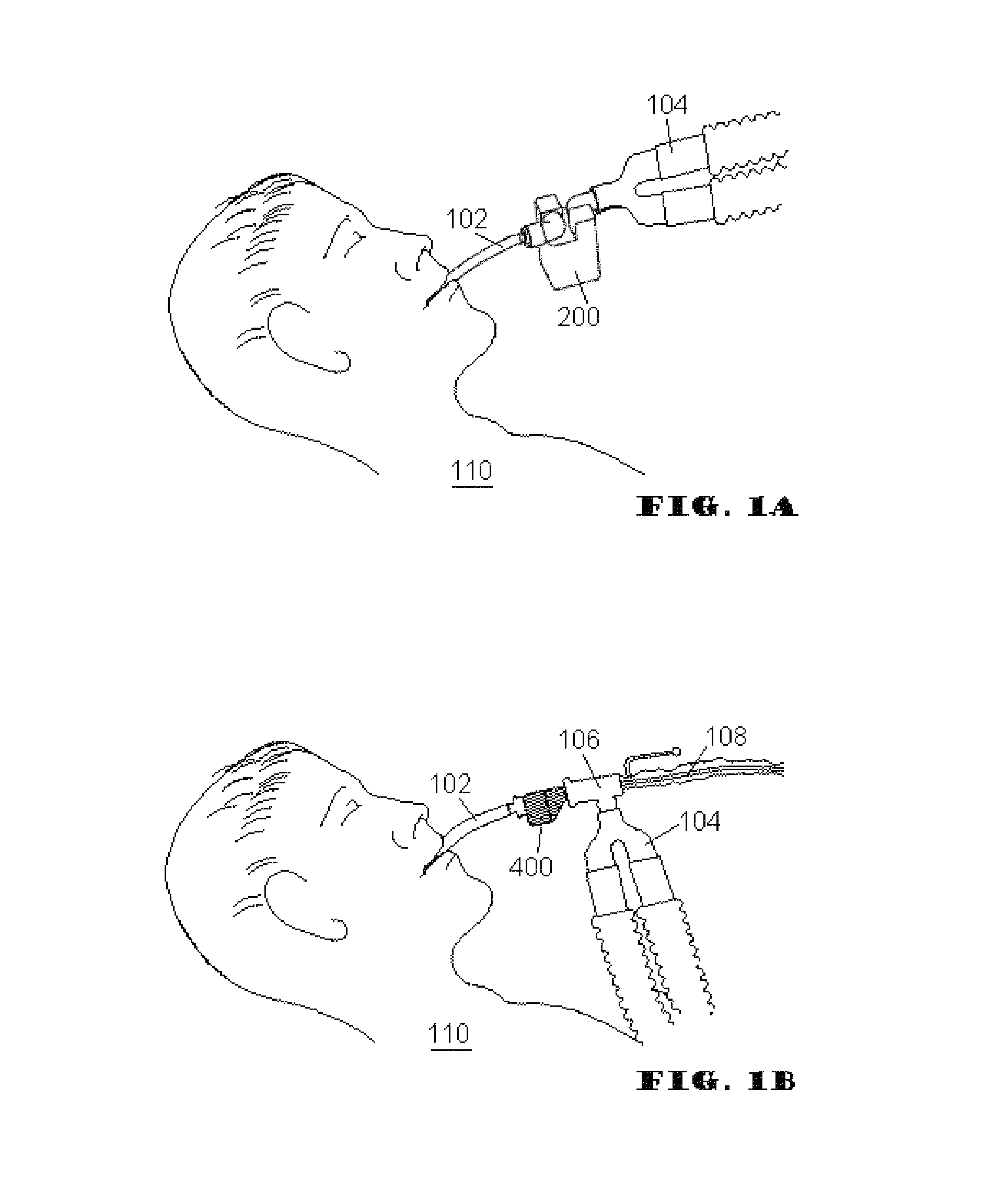
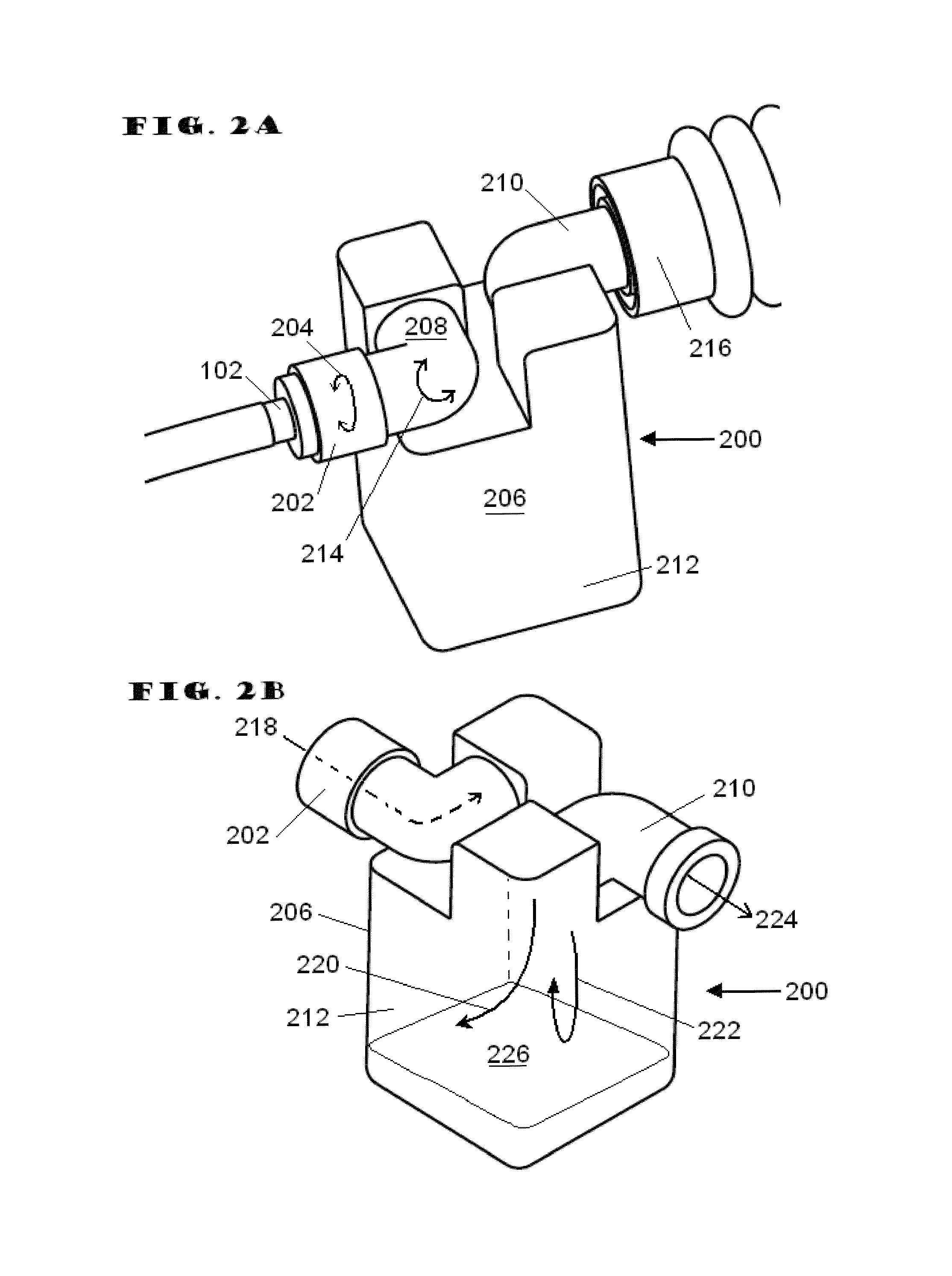
[0054]Embodiments of the present invention address deficiencies of the art in respect to artificial airways and respiratory secretion management, and provide a novel and non-obvious apparatus, system, and method for managing respiratory secretions and fluids in artificial airways. In an embodiment of the invention, a Respiratory Secretion Retention (RSR) device for connecting to an artificial airway can be provided. In an embodiment of the invention, a respirator...


PUM


Abstract

A novel and non-obvious apparatus, system, and method for managing respiratory secretions and fluids in sections of artificial airways. In an embodiment of the invention, a respiratory secretion retention (RSR) device configured to connect to an artificial airway can be provided. The respiratory secretion retention (RSR) device can include a housing that defines a passageway for the flow of respiratory gases, a chamber that is defined by the housing, where a portion of the chamber is configured to retain exhaled respiratory particulate and liquid, and at least one element configured to provide for repositioning at least a portion of the housing with respect to the artificial airway. In an aspect of this embodiment, the at least a portion of the housing can be repositioned with respect to the artificial airway without opening the artificial airway to the atmosphere.

Description

RELATED APPLICATIONS[0001]This application claims benefit and priority of U.S. Provisional Patent Application Ser. No. 61 / 104,597 filed Oct. 10, 2008, the entire contents of which are incorporated herein by reference thereto.BACKGROUND OF THE INVENTION[0002]1. Statement of the Technical Field[0003]The present invention relates to artificial airways and more particularly to an airway device for controlling respiratory secretions in artificial airways, and associated devices such as respiratory gas delivery devices.[0004]2. Discussion of the Related Art[0005]The use of artificial airways is a common method of maintaining an open airway for patients who require some type of respiratory assistance. Artificial airways come in a variety of options depending on the patient and level of respiratory intervention required. Large numbers of artificial airways have three common features. First, the artificial airway will be a flexible tube that extends into the patient's trachea. Second, most a...

Claims


Application Information

Patent Timeline
Patent Type & Authority Patents(United States)
IPC IPC(8): A61M1/00A62B7/10
CPCA61M16/0463A61M16/047A61M16/0488A61M16/0808A61M16/1045A61M16/0825A61M16/0833A61M16/0427
Inventor LANDIS, ROBERT M.LEWIS, CHARLES A.CARUSO, ANGELOSHER, BRUCECOLLAZO, LOUIS JAVIERCHANDRAN, SANJAY
Owner MERGENET MEDICAL
Learn More