
Interlock arrangement for controlling the neutral output of a portable generator

Active Publication Date: 2014-08-19
RELIANCE CONTROLS
View PDF26 Cites 14 Cited by
  • Summary
  • Abstract
  • Description
  • Claims
  • Application Information

AI Technical Summary

Benefits of technology

The invention provides an interlock arrangement for an electrical generator that can be used as a stand-alone power supply or in conjunction with a building's electrical system. The interlock arrangement prevents the need for expensive duplex receptacles with ground fault circuit interrupter devices and ensures the generator operates safely and efficiently without causing a ground fault risk. Overall, the invention expands the usability of the electrical generator and ensures safety and reliability during emergency or backup power situations.

Problems solved by technology

This system is more costly to buy and install.
As a result, when the generator is used as a stand-alone power supply or providing electrical power directly to one or more electrical devices without an electrical connection to the electrical wiring system of the building, ground fault protection is unnecessary because a path for current to flow back to the generator does not exist through the ground.
However, when a floating neutral generator is connected to the electrical system of a building, the generator becomes grounded through its electrical connection to the electrical system of the building.
As a result, there can be a ground fault risk when a floating neutral generator is connected to the electrical system of a building.
Since bonded neutral generators internally bond the neutral and ground conductors, costly GFCI devices are also used to provide ground fault protection primarily in construction applications where they are now required by the NEC.
Moreover, it has been found that connecting a bonded neutral generator to the electrical system of a home or building as a non separately derived system can result in “false” triggering of ground faults.
That is, the flow of electrical current to the safety grounding conductor of the generator has been known to trigger a ground fault circuit interrupter at the generator.
Many consumers are hesitant to tackle such a task and, moreover, it requires the consumer to remember to retie the generator neutral and the generator ground when the electrical generator is used to power electrical equipment directly rather than through the wiring of the home or building.
Thus, the duplex receptacles cannot be used to power tools or other electrical devices when the generator is connected to supply power to the electrical system of the home or building.
Moreover, the structure prevents the simultaneous availability of electrical power at both the multipole locking (or similar) receptacle used to connect the electrical generator to the electrical system of the home or building and the duplex receptacle(s).

Method used


Image

  • Interlock arrangement for controlling the neutral output of a portable generator
  • Interlock arrangement for controlling the neutral output of a portable generator
  • Interlock arrangement for controlling the neutral output of a portable generator

Examples


Embodiment Construction

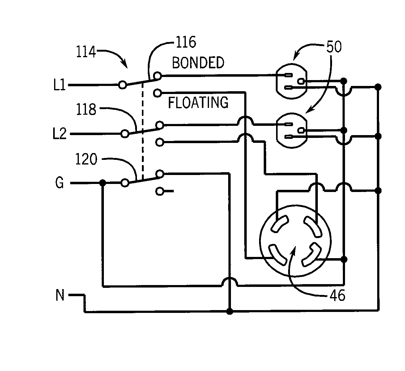
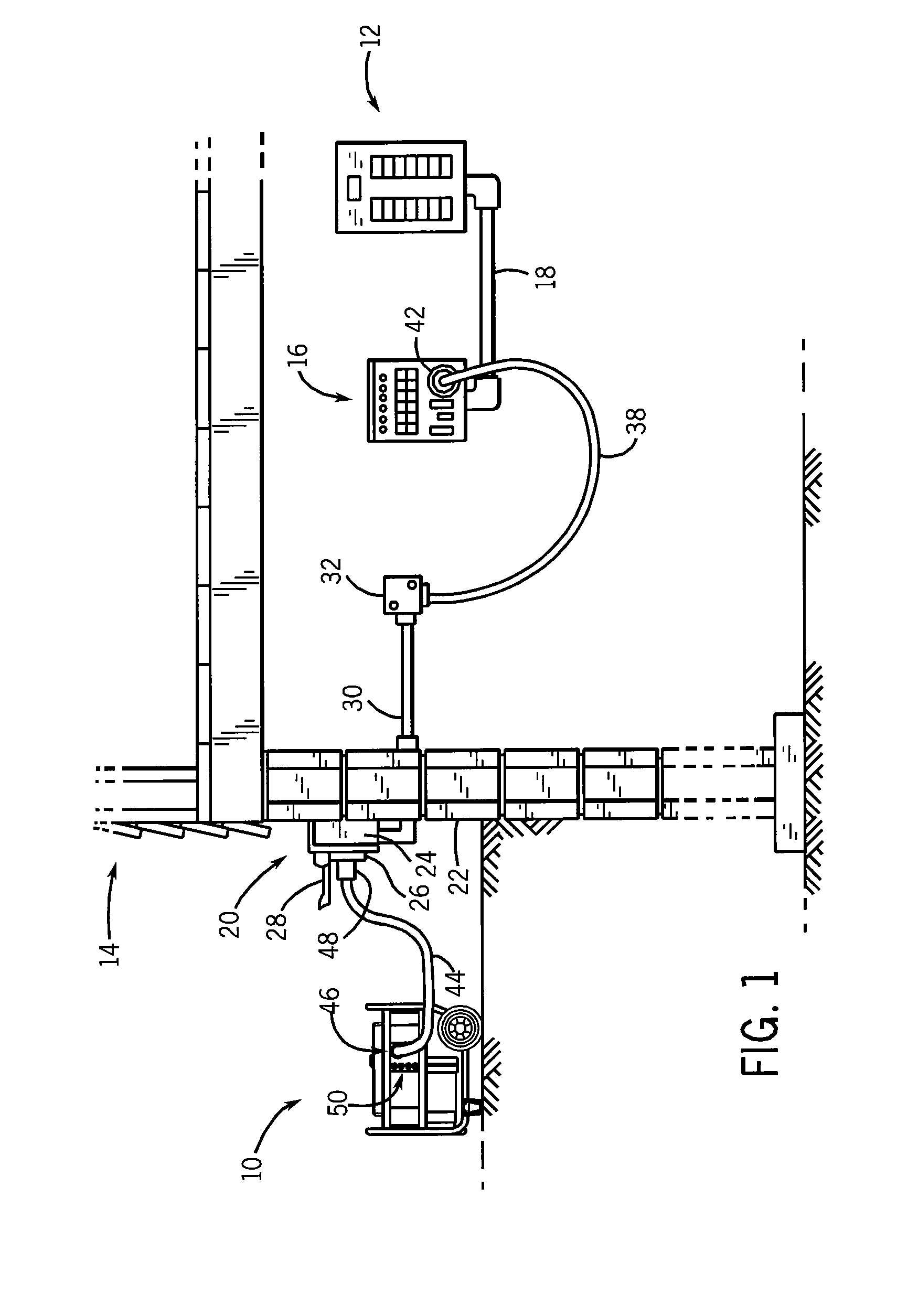
[0028]FIG. 1 shows a power inlet arrangement for interconnecting a portable generator 10 with a main electrical panel or load center 12 located in the interior of a building 14. In the power inlet arrangement of FIG. 1, a power transfer panel 16 is mounted adjacent main panel 12, and is interconnected therewith via a series of wires enclosed by a conduit 18 extending between main panel 12 and transfer panel 16. Transfer panel 16 may illustratively be a panel such as that manufactured by Reliance Controls Corporation of Racine, Wis.

[0029]A power inlet box 20 is mounted to the wall of building 14, shown at 22. Power inlet box 20 includes an external housing including a series of walls such as 24, and a receptacle 26 mounted to a front wall of the housing. A cover 28 is mounted to the front wall of the housing via a hinge structure, and is movable between an open position as shown in FIG. 1 and a closed position in which cover 28 encloses receptacle 26 when not in use. A conduit 30 ext...


PUM


Abstract

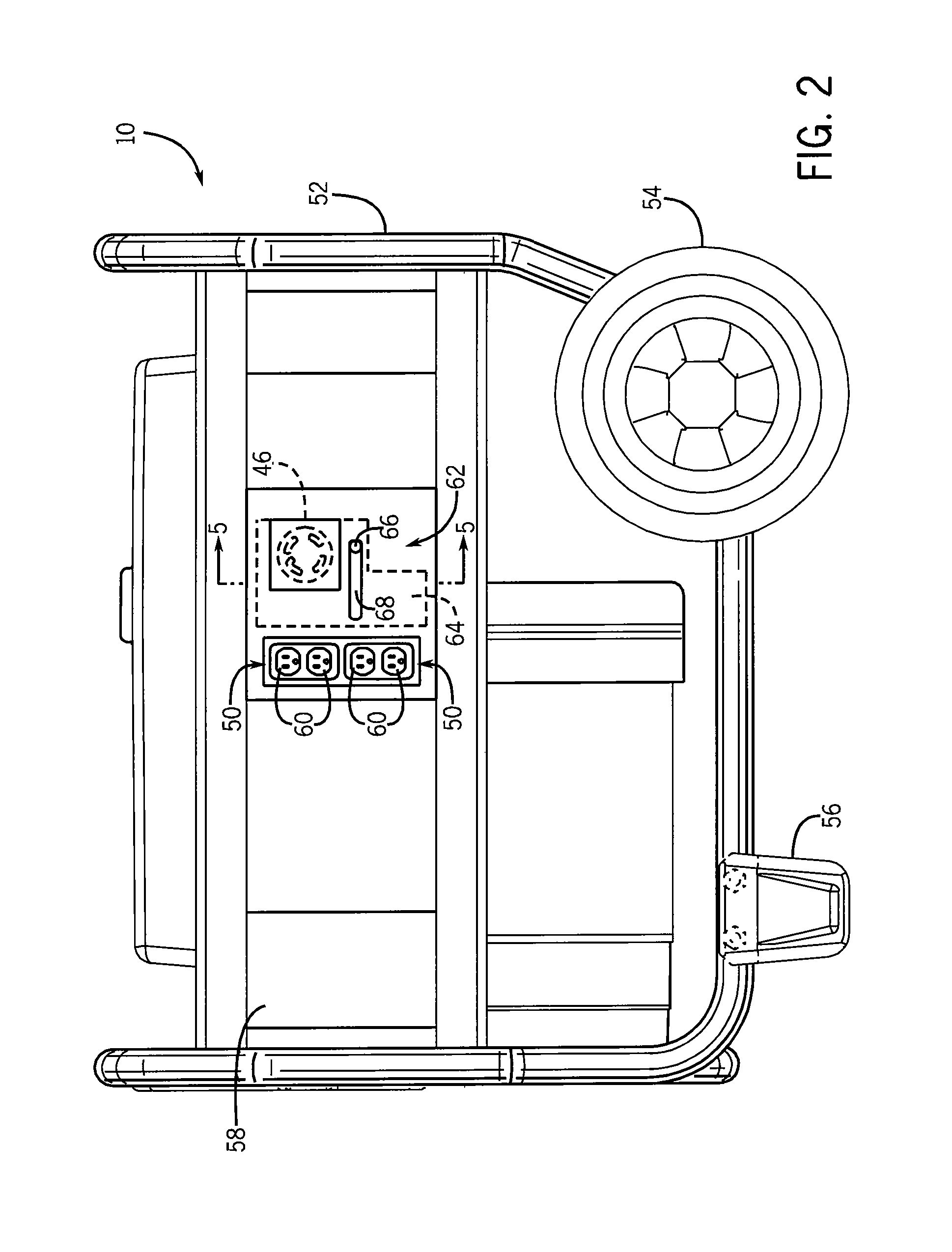
An interlock arrangement allows a floating neutral electrical generator having a receptacle, such as a duplex receptacle, absent GFCI protection to be used to provide electrical power to the electrical system of a home or other building during utility power interruption. The interlock arrangement includes structure to disable or prevent access to the duplex receptacle when the electrical generator is coupled to the power cord used to transfer electrical power from the generator to the electrical system of the building. Thus, the duplex receptacles cannot be used to power electrical devices when the generator is connected to supply power to the electrical system of the building. Conversely, when the generator is physically disconnected from the electrical system of the building, the interlock arrangement exposes or supplies power to the duplex receptacles, and may be configured to close access to the receptacle used for connecting to a building electrical system.

Description

CROSS-REFERENCE TO RELATED APPLICATION[0001]This application claims the benefit of U.S. Ser. No. 61 / 393,117 filed Oct. 14, 2010 and U.S. Ser. No. 61 / 309,624 filed Mar. 2, 2010, the disclosures of which are incorporated herein in their entirety.BACKGROUND AND SUMMARY OF THE INVENTION[0002]The present invention relates generally to electrical generators that can provide backup electrical power to an electrical system or that can be used as a stand-alone power supply for powered accessories, such as power tools. More particularly, the present invention is directed to an apparatus for selectively disabling outputs of an electrical generator based on the type of load placed on the electrical generator.[0003]In today's electrical supply systems, there are occasions when alternate sources of electrical power are necessary or desirable. For example, the capability of switching from utility power to emergency generator power is extremely important for many businesses, hospitals and industrie...

Claims


Application Information

Patent Timeline
IPC IPC(8): H02B1/16
CPCH01R13/447H01R24/78H02B1/16H01R13/703H01R25/006H01R2103/00F02B63/044H02J9/066H02J1/08H02J9/04Y10T307/398Y10T307/484
Inventor FLEGEL, MICHAEL O.FLEGEL, JEFFREY D.
Owner RELIANCE CONTROLS
Learn More