
Control unit for actuating a pressure valve, in particular a differential pressure valve of an aircraft cabin

a control unit and pressure valve technology, applied in the direction of valve details, valve types, air-treatment apparatus arrangements, etc., can solve the problems of inability to meet long-term behavior on the basis of conventional design and more stringent switching accuracy requirements, and achieve the effect of higher switching accuracy

Active Publication Date: 2014-08-19
NORD MICRO GMBH & CO OHG
View PDF38 Cites 1 Cited by
  • Summary
  • Abstract
  • Description
  • Claims
  • Application Information

AI Technical Summary

Benefits of technology

This invention is a control unit that helps to operate a pressure valve. The main goal is to improve the accuracy of the switching and make it more resilient to external influences that might affect its performance over the long term.

Problems solved by technology

In these well-known control units it has been found disadvantageous that the more stringent requirements with respect to the switching accuracy and the long-term behavior can no longer be fulfilled on the basis of the conventional design.

Method used


Image

  • Control unit for actuating a pressure valve, in particular a differential pressure valve of an aircraft cabin
  • Control unit for actuating a pressure valve, in particular a differential pressure valve of an aircraft cabin
  • Control unit for actuating a pressure valve, in particular a differential pressure valve of an aircraft cabin

Examples


Embodiment Construction

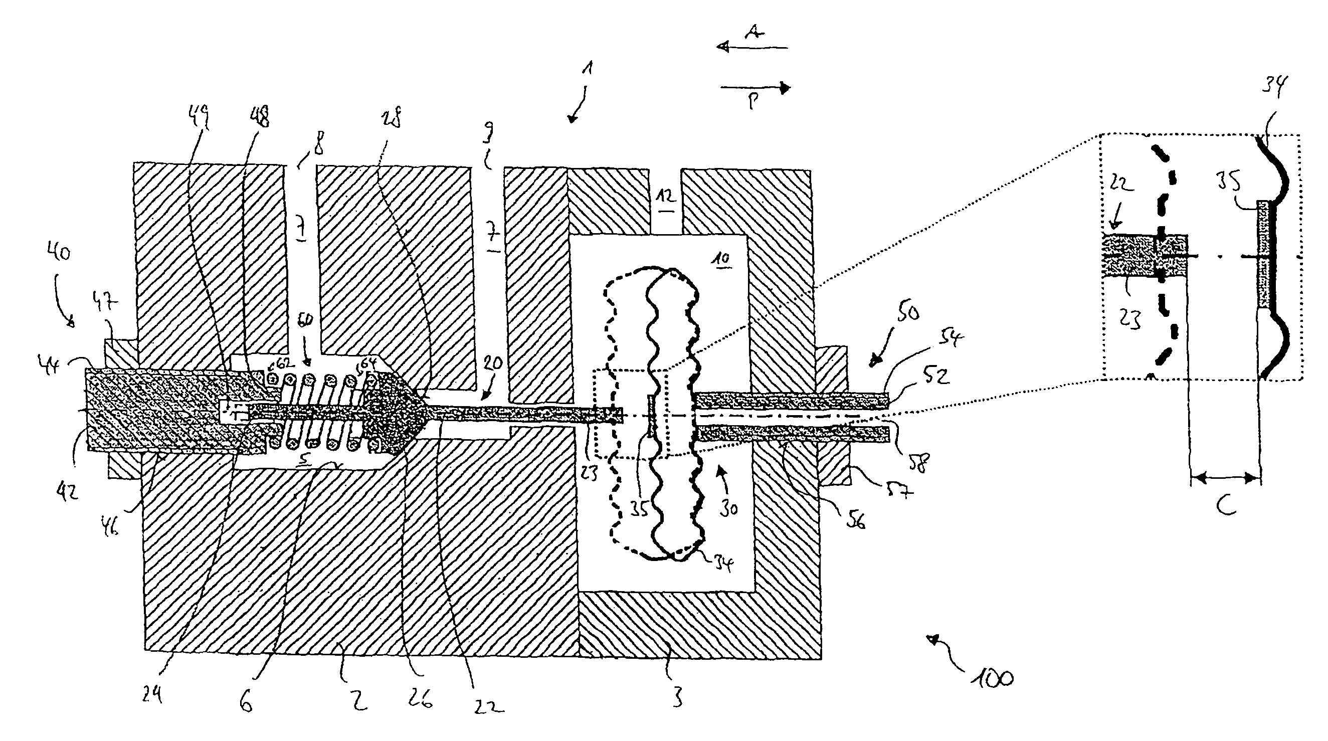
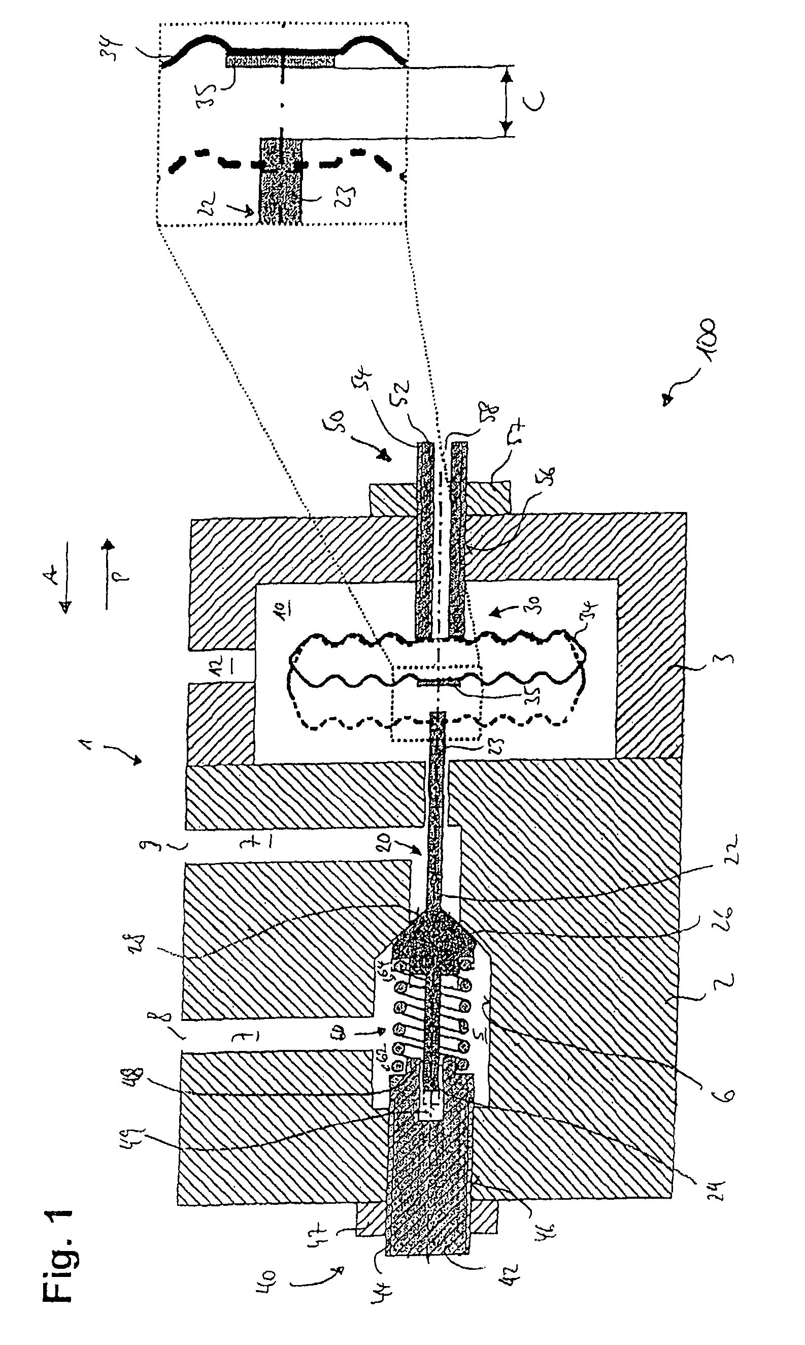
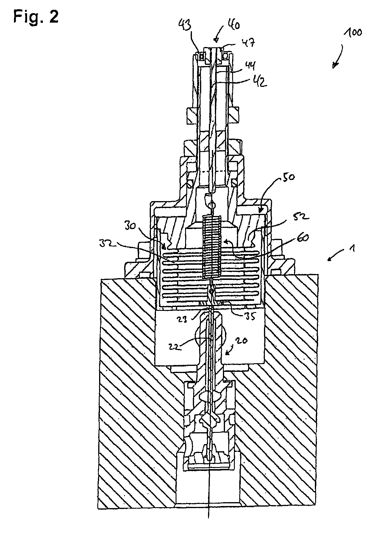
[0045]The control units 100 shown in FIGS. 1 and 2 are for operating a pressure relief valve of an aircraft cabin.

[0046]Control unit 100 shown in FIG. 1 comprises a housing 1 with a first housing section 2 and a second housing section 3. The two housing sections 2, 3 are connected with each other by screw connections. In the first housing section 2, a connecting line 7 is arranged with a first opening 8 and a second opening 9. A first chamber 5 is partially a part of connecting line 7 and has an inner side wall 6. The second housing section 3 has a second chamber 10 to which an ambient pressure can be applied via a channel 12.

[0047]Furthermore, control unit 100 comprises an actuating body 20 positively guided by first housing section 2 in the form of a valve tappet 22, and an actuator 30 arranged in second housing section 3 within second chamber 10. Valve tappet 22 hat a first end 23 and a second end 24 and, between these ends 23, 24, a sealing cone 26 as a valve body for closing or...


PUM


Abstract

A control unit (100) for actuating a pressure valve, particularly for actuating an overpressure valve in an aircraft cabin, comprises an actuating body (20) and a pressure-controlled actuator (30) for the actuation of the actuating body (20) as a function of a predetermined threshold pressure valve, wherein the threshold pressure value can be adjusted by means of an adjustment device (40, 50). The adjustment device (40, 50) comprises a first adjustment unit (40) and a second adjustment unit (50), wherein the actuating body (20) can be adjusted by means of the first adjustment unit (40), and the actuator (30) can be adjusted by means of the second adjustment unit (50).

Description

CROSS-REFERENCE TO RELATED APPLICATIONS[0001]This application is a §371 of International Application No. PCT / EP2007 / 063378 filed on Dec. 5, 2007 claiming §119 foreign priority to German Patent Application No. 10 2006 057 549.0 filed on Dec. 6, 2006.BACKGROUND OF THE INVENTION[0002](1) Field of the Invention[0003]The present invention relates to a control unit for actuating a pressure valve, in particular a pressure relief valve of an aircraft cabin. The control unit comprises an actuating body and a pressure-controlled actuator for operating the actuating body as a function of a predetermined threshold pressure value. The threshold pressure value is adjustable by an adjustment means.[0004](2) Description of Related Art[0005]To protect an aircraft cabin against overloading due to excessive differential pressure between the cabin pressure and the ambient pressure independently of electronic regulating systems, usually a safety valve is used with a control unit in the form of a mechani...

Claims


Application Information

Patent Timeline
Patent Type & Authority Patents(United States)
IPC IPC(8): F16K31/126F16K17/06B64D13/04F16K31/122
CPCF16K17/06F16K31/126Y10T137/7781
Inventor BRACKER, KLAUS-HEINRICHHAMRODI, ROBERTMAIER, RUDIGERSINGPIEL, ROLANDEISENLOHR, FELIXPOKERN, OLIVER
Owner NORD MICRO GMBH & CO OHG
Learn More