
Optical filter switching device

A filter switching and filter technology, which is applied in the direction of installation, optics, optical components, etc., can solve the problems of low filter switching precision switching mechanism, difficult control of servo system, insufficient motor moment of inertia, etc., to improve switching Accuracy, overcoming optical path difference, and overcoming the effect of span increase

Inactive Publication Date: 2021-03-30
CHANGCHUN INST OF OPTICS FINE MECHANICS & PHYSICS CHINESE ACAD OF SCI
View PDF13 Cites 0 Cited by
  • Summary
  • Abstract
  • Description
  • Claims
  • Application Information

AI Technical Summary

Problems solved by technology

[0003] Based on this, the present application aims to solve the problem that in the prior art, when the filter switching accuracy is low, the switching mechanism is huge, and the load for multi-stage filter switching is relatively large, the selected motor has insufficient driving capacity or the motor's moment of inertia is insufficient. To solve the problem of control, provide a compact filter switching device with precise positioning, so that its structure is simple and reliable, and it can meet the needs of theodolite optical system for dimming

Method used


Image

  • Optical filter switching device
  • Optical filter switching device
  • Optical filter switching device

Examples


Embodiment Construction

[0023] In order to facilitate the understanding of the present invention, the present invention will be described more fully below with reference to the associated drawings. Preferred embodiments of the invention are shown in the accompanying drawings. However, the present invention can be embodied in many different forms and is not limited to the embodiments described herein. On the contrary, these embodiments are provided to make the understanding of the disclosure of the present invention more thorough and comprehensive.

[0024] It should be noted that when an element is referred to as being “fixed” to another element, it can be directly on the other element or there can also be an intervening element. When an element is referred to as being "connected to" another element, it can be directly connected to the other element or intervening elements may also be present.

[0025] Unless otherwise defined, all technical and scientific terms used herein have the same meaning as...


PUM


Abstract

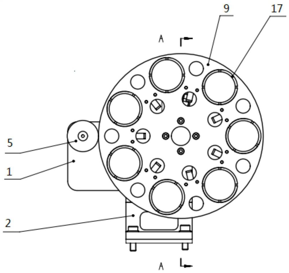
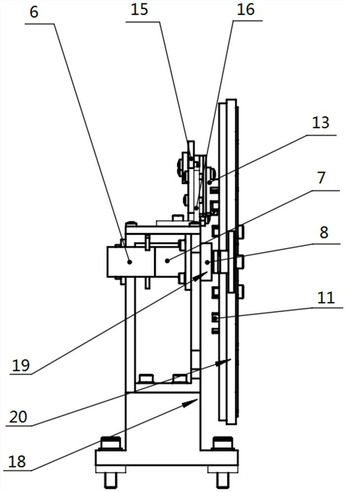
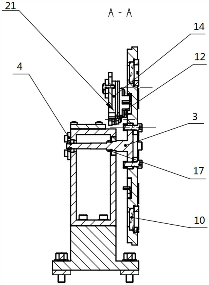
The invention provides an optical filter switching device which comprises a rack, a transmission assembly, an optical filter assembly and a limiting assembly, wherein the optical filter assembly is installed on the rack through a rotating shaft and can move in the transverse direction and the longitudinal direction of the rack, and the transmission assembly and the limiting assembly are both installed on the rack; and the transmission assembly drives the optical filter assembly to move around the rotating shaft through a gear, and the limiting assembly controls the rotating angle of the optical filter assembly. The optical filter switching device is simple and compact in structure and can meet the requirement of a theodolite optical system for dimming.

Description

technical field [0001] The invention relates to the technical field of optical device light adjustment elements, in particular to an optical filter switching device. Background technique [0002] In the shooting range measurement process, the optical filter is used as a light-adjusting element in the theodolite optical system, and its switching accuracy directly affects the measurement results. At present, most of the filter switching is a linear switching structure. This structure is easy to locate and has high precision, but it will occupy a lot of space, which will increase the span of the theodolite tracking frame, increase the overall weight and cost, and reduce the system rigidity. . The optical filter switching structure described in patent CN108957673A adopts the switching mode of polyhedral density disk rotation. Although the structure is compact, the processing of the polyhedral density disk is complicated and it is difficult to achieve high-precision positioning....

Claims


Application Information

Patent Timeline
Patent Type & Authority Applications(China)
IPC IPC(8): G02B7/00G01C1/02
CPCG02B7/006G01C1/02
Inventor 王晓明牛文达
Owner CHANGCHUN INST OF OPTICS FINE MECHANICS & PHYSICS CHINESE ACAD OF SCI
Learn More