
Broadhead arrow tip and associated methods

a broadhead arrow and arrow tip technology, applied in the field of mechanical broadhead arrow tips, can solve the problems of reducing the number of problems of avid archers, and reducing the number of targets lost, so as to reduce the weight and manufacturing complexity of the arrow tip, reduce the vibration of the blade during flight, and minimize the movement of the parts.

Inactive Publication Date: 2014-08-12
MILES CHRISTOPHER RAY
View PDF4 Cites 9 Cited by
  • Summary
  • Abstract
  • Description
  • Claims
  • Application Information

AI Technical Summary

Benefits of technology

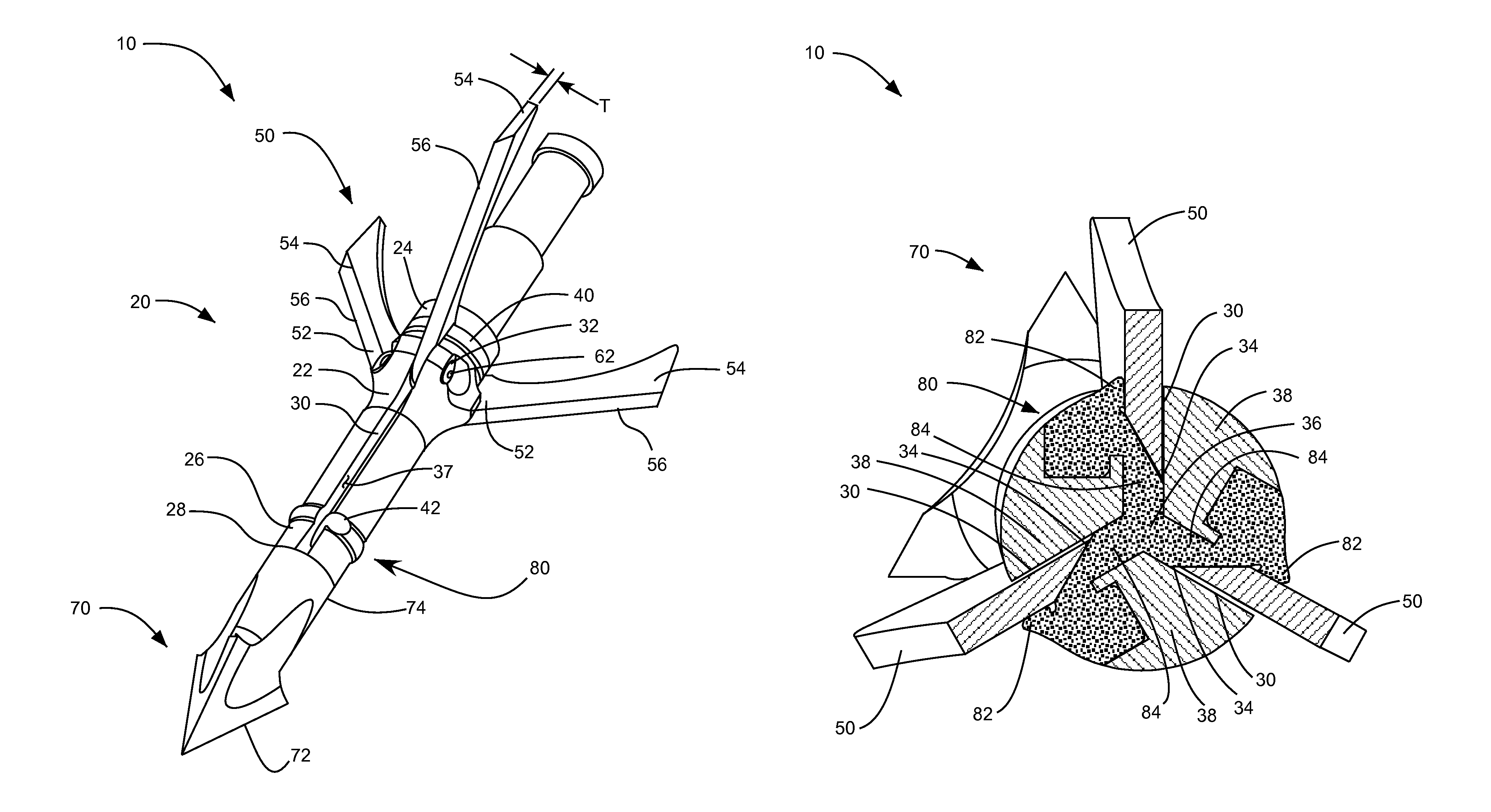
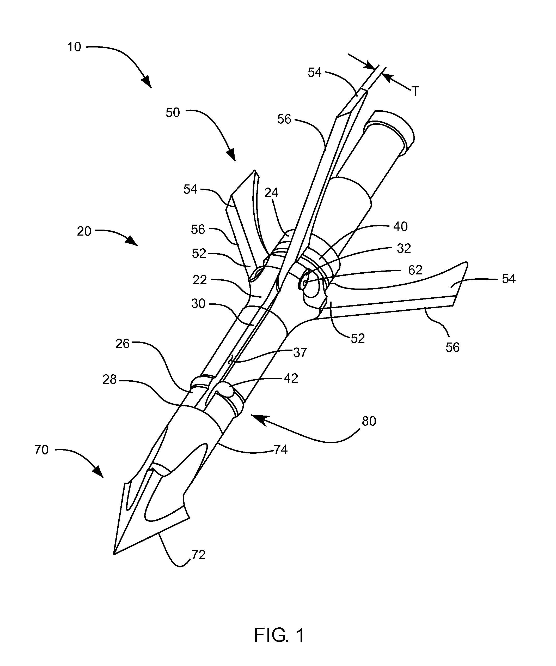
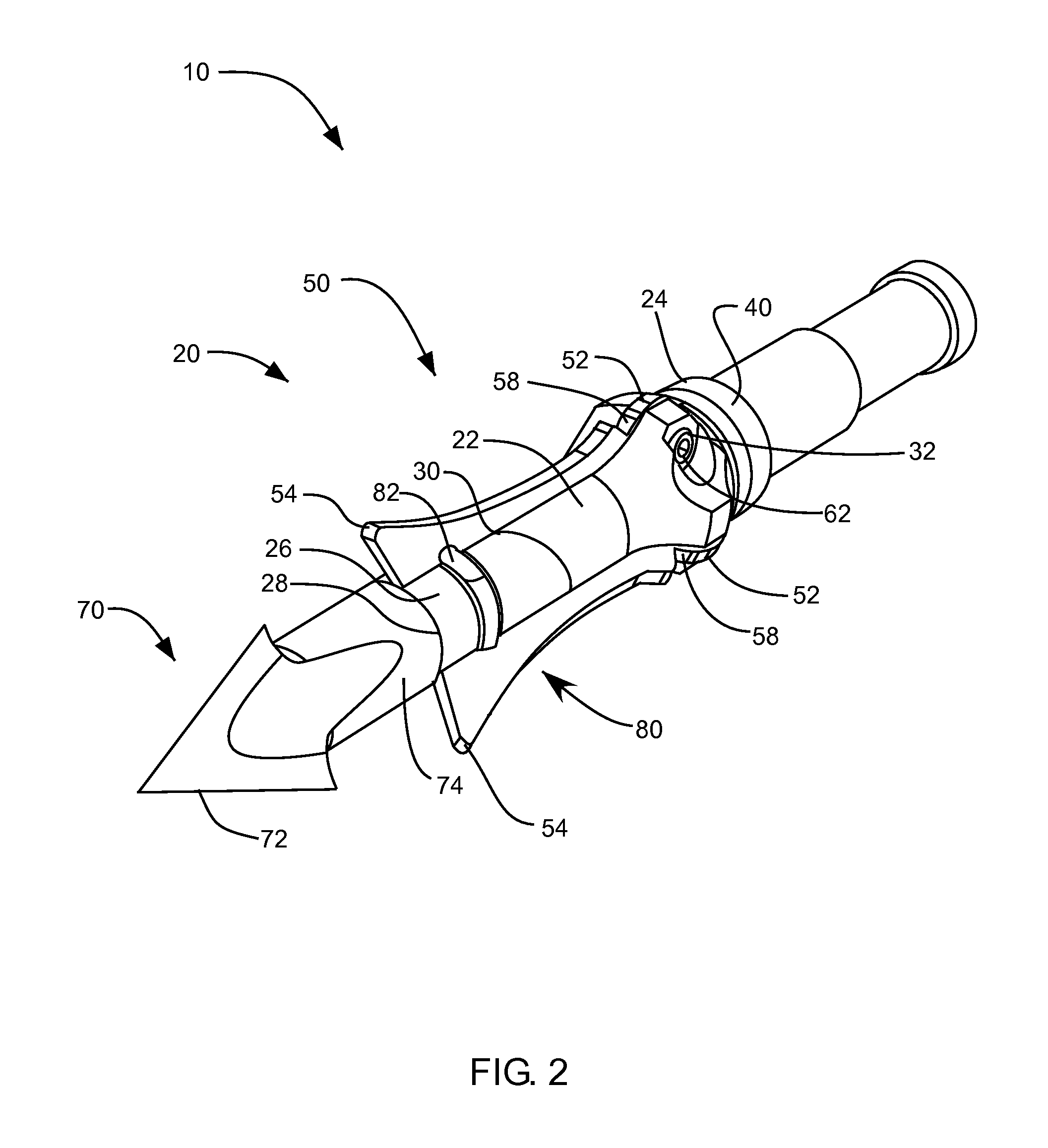
The present invention is about a new kind of mechanical broadhead arrow tip that has re-usable parts that keep the blades in a safe position during flight and allow them to move when impact occurs. The tip also has minimal moving parts, which reduces weight and manufacturing complexity. Additionally, the tip helps to reduce vibration of the blades during flight by wiggling them against the heart body of the arrow.

Problems solved by technology

Unfortunately, broadhead arrow tips using such expendable retention devices can cause a number of problems for avid archers.
For example, the retention devices can fail prematurely due to operating conditions such as environmental exposure, extreme velocities of the arrows, and the like.
It will be appreciated that premature failure of the retention device can cause aerodynamic problems for the arrow in flight, which may result in target loss, non-lethal wounding of prey and laceration hazards to the archer.
Moreover, expendable retention devices need to be replaced after every use which increases the costs and decreases the efficiency of the broadhead to the archer.
Another problem of many broadhead arrow tips is they have multiple moving parts that can cause balance and aerodynamic problems for the arrow in flight.
Additionally, having many moving components in one arrow tip generally increases the amount of kinetic energy needed in order to deploy the blades.
Using kinetic energy to deploy the blades reduces the amount of energy available to the arrow for penetrating a target.
Moreover, many moving parts can increase the overall manufacturing costs of the arrow.
Yet another problem with some mechanical broadhead arrow tips is that the blades can vibrate during flight which can cause a whistling noise as the arrow flies.
Such noises have been known to startle animals, causing them to bolt and leaving the bow hunter without a kill.

Method used


Image

  • Broadhead arrow tip and associated methods
  • Broadhead arrow tip and associated methods
  • Broadhead arrow tip and associated methods

Examples


Embodiment Construction

[0028]Reference will now be made to the exemplary embodiments illustrated in the drawings, and specific language will be used herein to describe the same. It will nevertheless be understood that no limitation of the scope of the invention is thereby intended. Alterations and further modifications of the inventive features illustrated herein, and additional applications of the principles of the inventions as illustrated herein, which would occur to one skilled in the relevant art and having possession of this disclosure, are to be considered within the scope of the invention.

[0029]The embodiments of the present invention described herein generally provide for a broad head arrow tip with extendable blades that move between a retracted, stowed position and an extended, deployed position. During flight the blades are positioned and retained in the retracted position. Upon impact, as the arrow head travels through a target, the blades are deployed to the extended position thereby increas...


PUM


Abstract

A blade-opening arrowhead device includes an arrowhead body having a plurality of longitudinal blade slots on an outer surface and a flexible wedge slot extending through a center portion of the body. A blade is pivotally disposable in one of the blade slots and pivotable between a retracted position and a deployed position. A flexible wedge is disposable in the flexible wedge slot. The flexible wedge is configured to apply a wedging force against the blade in the retracted position to maintain the blade in the retracted position until a sufficient external force overcomes the wedging force and pivots the blade to the open position.

Description

BACKGROUND OF THE INVENTION[0001]1. Field of the Invention[0002]The present invention relates generally to archery products and more particularly to mechanical broadhead arrow tips.[0003]2. Related Art[0004]Many mechanical broadhead arrow tips have movable blades that can be stowed during flight and deploy upon impact. The blades are stowed during flight to provide aerodynamic stability to the arrow during flight. Upon impact the blades are deployed to an extended position that enlarges the cutting profile of the arrow tip.[0005]Some mechanical broadhead arrow tips use an expendable retention device to retain the movable blades in the stowed position. Such expendable retention devices usually need to be replaced after each use of the arrow. For example, some broadheads use an elastomeric o-ring that that stretches around the outside of the arrowhead and exerts a resistive force against the blades to hold the blades in the stowed position. When the arrow impacts its target the impact...

Claims


Application Information

Patent Timeline
Patent Type & Authority Patents(United States)
IPC IPC(8): F42B6/08
CPCF42B6/08
Inventor MILES, CHRISTOPHER, RAY
Owner MILES CHRISTOPHER RAY
Learn More