Ski or skate binding

a technology of skis and bindings, applied in the field of skis or skate bindings, can solve the problems of affecting the push-off negatively, the support around the foot is not optimal, and the ability of ice skaters is limited, so as to improve the ability of ice skaters and improve the comfort and performance of skating/skiing

Active Publication Date: 2014-08-12
FLOW MOTION TECH AB
View PDF50 Cites 8 Cited by
  • Summary
  • Abstract
  • Description
  • Claims
  • Application Information

AI Technical Summary

Benefits of technology

[0008]It is an object of the present invention to improve the ability for ice skaters and skiers to shift the center of gravity along the length of the foot, from heel to toe, with an even pressure, to improve skating / skiing comfort and performance.
[0011]The present binding provides a stepless rolling motion between the upper and the lower chassis, which provides a good ability for ice skaters and skiers to shift the center of gravity along the length of the foot, from heel to toe, with an even pressure. The rolling motion enables users to use a stiffer shoe and / or a shoe with higher shaft for more support of the foot and leg, facilitating a more powerful push off. The stepless rolling motion alone, however, also facilitates a more powerful push off since the ability to shift the center of gravity along the length of the foot with even pressure is a more natural movement than the movement existing technologies within the area provides. The rolling motion also enables the skater to push off with a larger angle that is more beneficial and allows for use of large muscle groups during a larger part of the push off.
[0012]The skater's / skier's balance is improved since the rolling motion makes it easier to parry / compensate unevennesses in the underlying surface, i.e. ice or snow. The invention further enables a vehicle with a prolonged, and flatter, contact surface against the ice / snow, compared to normal, thereby providing better glide, at the same time as it allows for the skater to quickly shift the weight from heel to toe, thus enabling for quicker, shorter turns and directional changes.
[0016]In accordance with an embodiment of the binding, the first and / or the second contact surface is arranged to be interchangeable. This enables the user to easily adjust the range of movement between the upper and the lower chassis.
[0017]In accordance with an embodiment of the binding, at least one interchangeable contact surface includes a separate front and a separate rear portion. This enables the user to combine different curvatures.
[0018]In accordance with an embodiment of the binding, at least one of the first or the second interchangeable element is arranged to be movable in the longitudinal direction of the binding. This enables the user to easily adjust where the curvature is arranged under the foot.

Problems solved by technology

The push-off is however limited by the fact that the attachment point is more or less fixed.
This leads to the support around the foot not being optimal, which affects the push-off negatively.
However, they are not helped by a clap functionality since they also must be able to handle quick turns.
This means that the skater is forced to use a low shoe that does not provide optimal support.
However, a disadvantage with the short contact surface is that it glides less efficiently.
This is brought about by the skater being more affected by unnecessary movements and unevenness in the underlying surface than if he would have been skating on a vehicle with a long contact surface against the ice.
However, with the known binding the skater is not able to shift the center of gravity along the length of the foot with an even pressure.
With the known binding the skater is not able to shift the center of gravity along the length of the foot with an even pressure.

Method used


Image

  • Ski or skate binding
  • Ski or skate binding
  • Ski or skate binding

Examples


Embodiment Construction

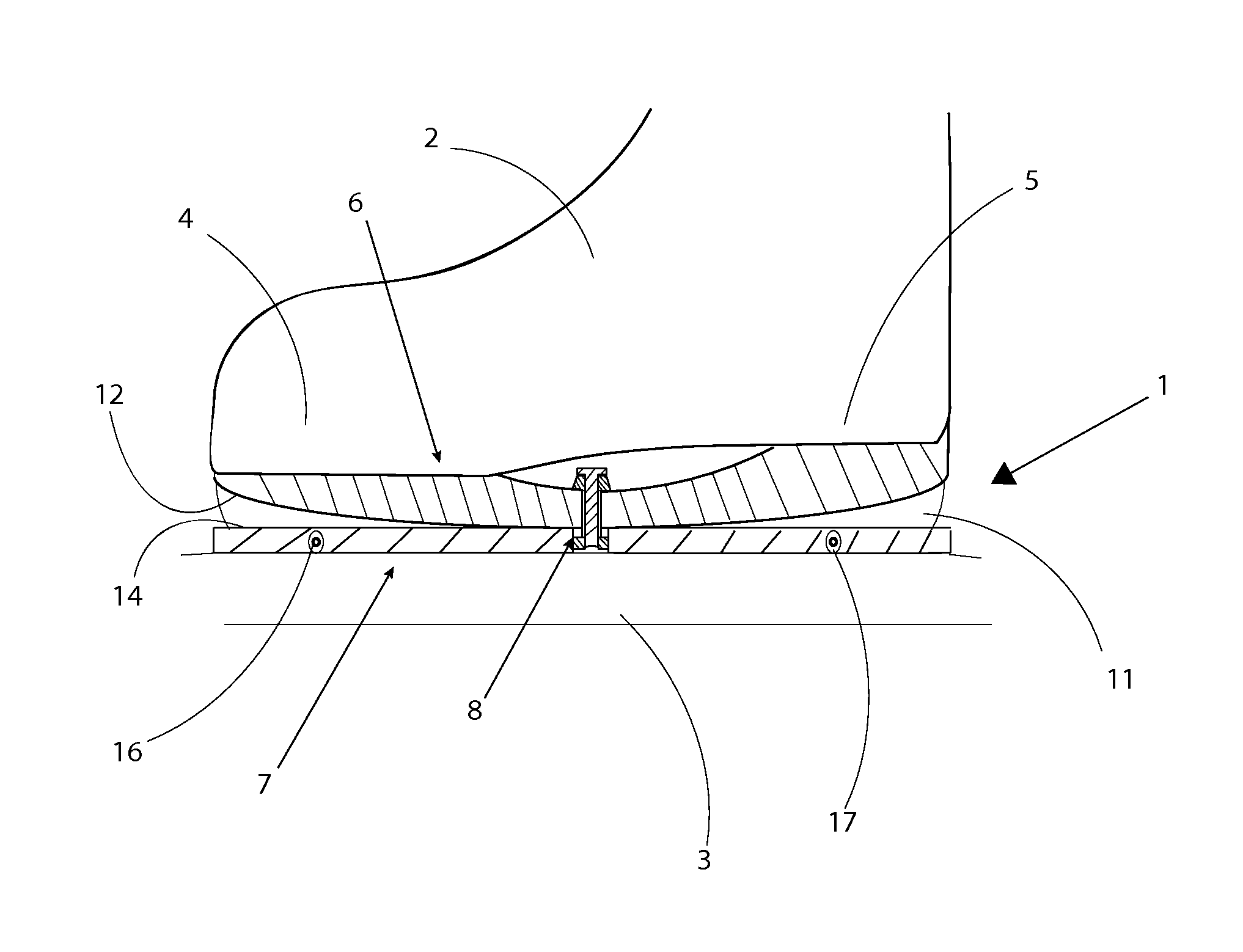
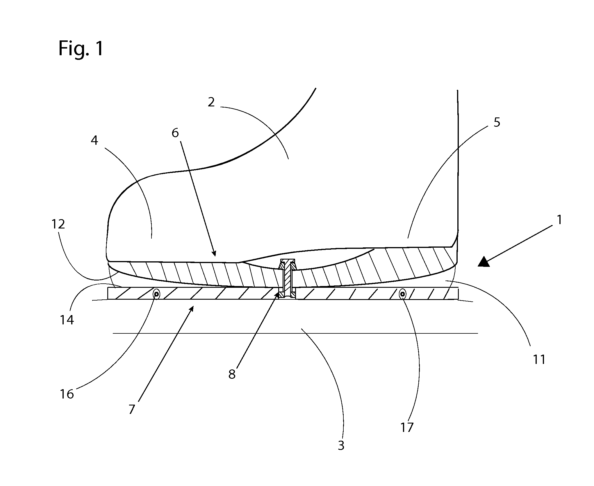
[0040]With reference to FIG. 1, an embodiment of a binding 1 in accordance with the present invention is shown. The binding 1 is arranged to connect a shoe 2 to a skate for skating on ice or to a ski, hereafter referred to as the vehicle 3. For the avoidance of doubt, it should be noted that the skate could either be comprised by a separate blade or a blade integrated in some form of skate chassis. The shoe 2 has a toe area 4 and a heel area 5. The shoe 2 consists of any type of shoe suitable for the purpose. The type of shoe does not limit the scope of protection of the present invention and is therefore not described in more detail in this patent application. The vehicle 3 is comprised of a type of vehicle suitable for the purpose. The type of vehicle is not limiting for the scope of protection of the present invention, and is therefore not described in more detail in this patent application. The binding 1 includes at least one chassis including at least one upper chassis section ...


PUM


Abstract

A binding for a vehicle, such as a skate for skating on ice or a ski. The binding has an upper chassis section and a lower chassis section, which are interconnected by means of coupling means. The upper chassis section and the lower chassis section are arranged to be rollable relative to each other in the vehicle's longitudinal direction. The binding includes a first and a second contact surface at least one of the first and the second contact surface being curved. Thereby a stepless rolling motion between the upper chassis and the lower chassis is provided for, allowing the chassis to rock both backwards and forwards in relation to each other.

Description

FIELD OF THE INVENTION[0001]The present invention relates to an integrated or separate binding for the attachment of a shoe to a skate for skating on ice or to a ski. More specifically, the present invention concerns a binding in accordance with the claims.BACKGROUND OF THE INVENTION[0002]When skating on ice or snow, it is advantageous to have a skate or a ski, below referred to as vehicles, with as long a contact surface against the ice / snow as possible during the gliding phase. The skater / skier hereby becomes less sensitive to imperfections in the underlying surface and to inadequate technique. A short contact surface against the ice / snow provides advantages during quick maneuvers and push-off. Some existing technical solutions and their advantages and disadvantages are described below.[0003]For skating on vehicles with long contact surfaces against the ice / snow, there are currently a number of technical solutions based on a so-called “clap” functionality, herein used for a ski or...

Claims


Application Information

Patent Timeline
Patent Type & Authority Patents(United States)
IPC IPC(8): A63C1/28
CPCA63C1/28A63C1/22A43B5/0417A43B5/0421A63C9/02A43B5/1641A63C17/067A43B5/16A63C1/16
Inventor MARS, PER
Owner FLOW MOTION TECH AB
Why Eureka
Try Eureka