
Front fork spring leg

a front fork and spring technology, applied in the direction of shock absorbers, steering devices, cycle equipments, etc., can solve the problems of impaired suspension function, abrasive dust produced by the piston ring, and impaired sealability of the outward-facing seal member, so as to prevent the abrasive dust from the piston ring

Active Publication Date: 2014-08-12
HITACHI ASTEMO LTD
View PDF15 Cites 4 Cited by
  • Summary
  • Abstract
  • Description
  • Claims
  • Application Information

AI Technical Summary

Benefits of technology

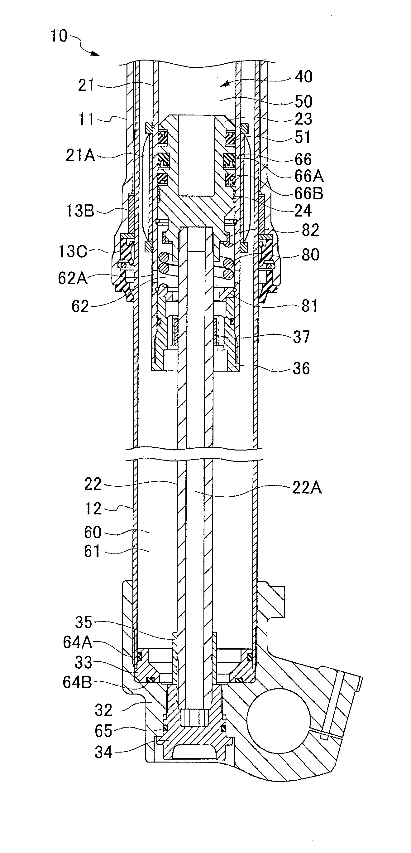
[0018]Accordingly, no abrasive dust from the piston ring will be moved toward the inward-facing seal member, passing the outer periphery of a lip of the outward-facing seal member due to an orientation of the lip. As a result, the inward-facing seal member is prevented from being scratched by the abrasive dust from the piston ring, a sealability of the inward-facing seal member can be ensured, and leakage of an air pressure from the inner air spring chamber is prevented. Thus, the spring force of the air spring in the inner air spring chamber can be maintained stably, and a suspension function is not impaired.
[0019]Further, it can be ensured that no abrasive dust from the piston ring will pass an outer periphery of a lip of the outward-facing seal member due to the orientation of the lip. This makes it possible to prevent the outward-facing seal member from being scratched by the abrasive dust from the piston ring, to ensure the sealability of the outward-facing seal member, to prevent a lubricating oil in the lower part of the outer air spring chamber from entering the inner air spring chamber, and hence to prevent an air pressure in the inner air spring chamber from raising to a critical pressure.
[0021](b) The outward-facing seal member described in (a) above is arranged in plurality at a plurality of positions along an axial direction on the outer periphery of the guide of the guide rod. This makes it possible to further prevent the abrasive dust from the piston ring from passing the outer peripheries of the lips of the plurality of outward-facing seal members arranged in series, and to prevent the inward-facing seal member and the outward-facing seal member from being scratched by the abrasive dust from the piston ring more reliably.
[0025](d) There is provided, in the inside of the guide cylinder, a rebound air spring chamber interposed and defined between a rod guide provided on the guide cylinder for receiving and supporting the guide rod inserted therein, and the guide of the guide rod inserted in the guide cylinder. The abrasive dust from the piston ring can be prevented, by the features (a) and (b), from passing the outer periphery of the lip of the outward-facing seal member due to an air pressure in the rebound air spring chamber becoming high on the extended side during an extension stroke.

Problems solved by technology

However, in the spring leg described in the Japanese Patent Application Laid-Open (kokai) No. 2012-092945, the piston ring is located between the inward-facing seal member and the outward-facing seal member on the outer periphery of the guide of the guide rod, and this piston ring produces abrasive dust.
If the inward-facing seal member is scratched, a sealability of the inward-facing seal member will be impaired, which will reduce the spring force of the air spring in the inner air spring chamber, possibly leading to an impaired suspension function.
If the outward-facing seal member is scratched, a sealability of the outward-facing seal member will be impaired, which will cause the lubricating oil in the lower part of the guide cylinder to enter the inner air spring chamber, and the air pressure in the inner air spring chamber will be increased to the critical pressure by the increase of the oil entering into the chamber.

Method used


Image

  • Front fork spring leg
  • Front fork spring leg
  • Front fork spring leg

Examples


first embodiment (figs.1 to 4)

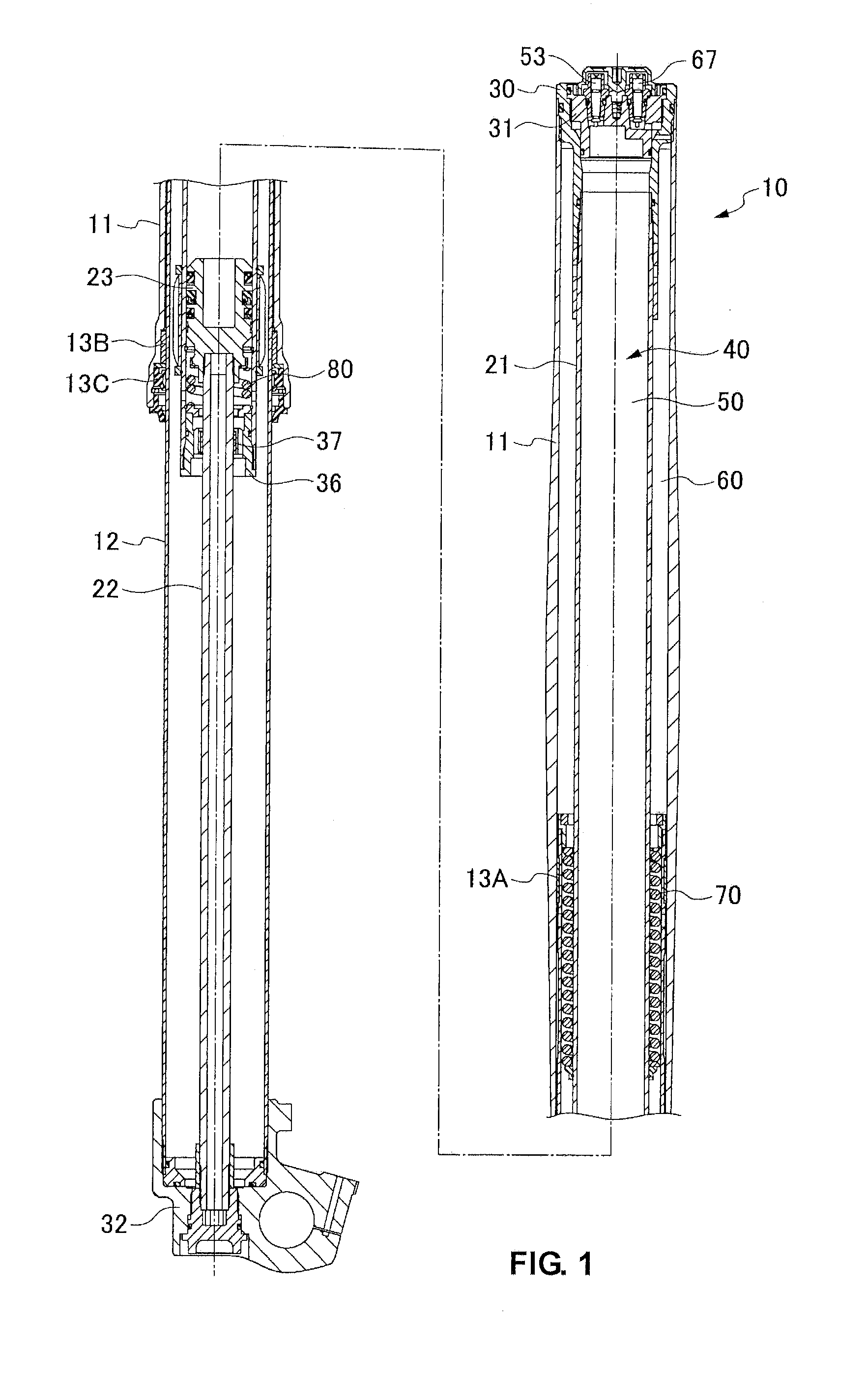
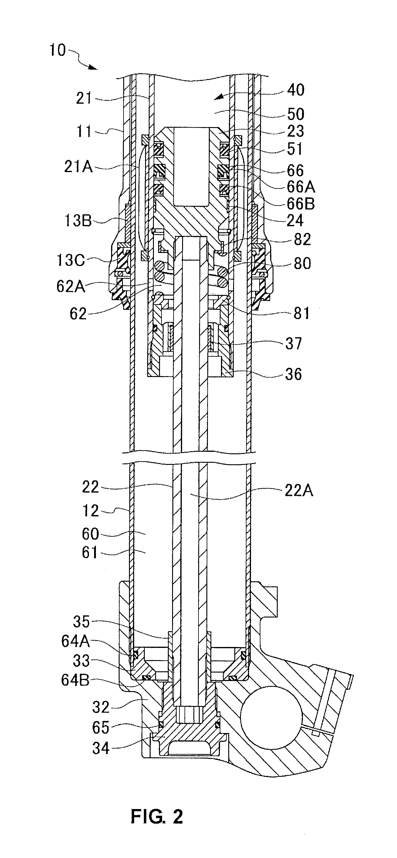
[0034]First Embodiment (FIGS. 1 to 4)

[0035]A spring leg 10 according to a first embodiment of the invention shown in FIGS. 1 to 3 constitutes at least one of right and left legs of a front fork of a motorcycle or the like. This spring leg 10 has no built-in damper, but has a built-in suspension spring formed of an air spring. The other leg of the front fork is formed of a damper leg having a built-in damper but having no built-in suspension spring. However, the other leg may be a spring leg similar to the spring leg 10.

[0036]As shown in FIGS. 1 to 3, the spring leg 10 is formed by inserting an axle-side tube (inner tube) 12 into a vehicle body-side tube (outer tube) 11 in a slidable manner while interposing bushes 13A, 13B therebetween and being sealed with a seal member 13C. The spring leg 10 has a guide cylinder 21 that is suspended at a central portion of the inside of the vehicle body-side tube 11, and a guide rod 22 that is erected at a central portion of the inside of the axle...

second embodiment (figs.5 to 8)

[0062]Second Embodiment (FIGS. 5 to 8)

[0063]A spring leg 110 according to a second embodiment is substantially the same as the spring leg 10 according to the first embodiment. The spring leg 110 has no built-in damper but has a built-in suspension spring 120 formed of air springs (an air spring in an inner air spring chamber 130, an air spring in an outer air spring chamber 140, and an air spring in a rebound air spring chamber 150).

[0064]As shown in FIGS. 5 to 7, the spring leg 110, except a suspension spring 120, is the same as the spring leg 10 according to the first embodiment. Therefore, like components are denoted by like reference numerals and description thereof will be omitted. The suspension spring 120 of the spring leg 110 is configured as described below.

[0065]The spring leg 110 has an inner air spring chamber 130 defined by the front end guide 23 of the guide rod 22 in the inside of the guide cylinder 21, and an outer air spring chamber 140 defined by the vehicle body-s...


PUM


Abstract

A front fork spring leg, which is capable of stably maintaining air spring, has an inward-facing seal member, an outward-facing seal member, and a piston ring arranged on an outer periphery of a guide of a guide rod sequentially in this order along an axial direction of the guide from a side close to an inner air spring chamber toward a side far from the inner air spring chamber. The inward-facing seal member has a lip which is slidably in contact with an inner periphery of the guide cylinder, with this lip being oriented toward the inner air spring chamber. The outward-facing seal member has a lip which is slidably in contact with the inner periphery of the guide cylinder, with this lip being oriented in an opposite direction to the inner air spring chamber.

Description

CROSS-REFERENCE TO RELATED PATENT APPLICATIONS[0001]This application claims the benefit of Japanese Patent Application No. 2012-043358, filed Feb. 29, 2012, which is incorporated by reference herein.FIELD OF THE INVENTION[0002]This invention relates to a front fork spring leg suitable for use in a motorcycle or the like.BACKGROUND OF THE INVENTION[0003]One conventional front fork comprises, as described in Japanese Examined Utility Model Application Publication No. S49-1162, a spring leg which does not have a built-in damper but have a built-in suspension spring formed of a metal spring for suspending a vehicle weight.[0004]The applicant of this invention proposes, as described in Japanese Patent Application Laid-Open (kokai) No. 2012-092945, to use an air spring as the suspension spring incorporated in a spring leg in order to reduce the weight of the front fork and to reduce the vehicle weight.[0005]The spring leg described in Japanese Patent Application Laid-Open (kokai) No. 2012...

Claims


Application Information

Patent Timeline
Patent Type & Authority Patents(United States)
IPC IPC(8): B62K25/08
CPCB62K25/08F16F9/0209F16F9/0236F16F9/0218
Inventor AOKI, YASUHIRO
Owner HITACHI ASTEMO LTD
Learn More