
Solenoid valve

a solenoid valve and valve body technology, applied in the direction of valve housings, valve operating means/release devices, machines/engines, etc., can solve the problems of deteriorating accuracy in controlling flow rate, difficulty in accurately regulating fluid flow, safety problems, etc., to ensure sealability and simplify structure

Active Publication Date: 2021-11-18
HYUNDAI MOTOR CO LTD +1
View PDF0 Cites 0 Cited by
  • Summary
  • Abstract
  • Description
  • Claims
  • Application Information

AI Technical Summary

Benefits of technology

The technical effect of this patent is to provide a solenoid valve that has good sealability and a simple design.

Problems solved by technology

Meanwhile, if sealing performance of the solenoid valve is not ensured, there may be problems in that it is difficult to accurately regulate (turn on / off) the flow of the fluid, and accuracy in controlling the flow rate deteriorates, and a safety accident may occur.
For example, if hydrogen leaks from the solenoid valve mounted in a hydrogen supply line required to have high sealability, there may be safety problems such as damage to components, explosion, fires, and the like.
However, in the related art, because a shut-off solenoid valve for regulating a flow of a fluid and a flow rate control solenoid valve for controlling a flow rate of the fluid need to be separately and independently provided in order to ensure stability and sealability of the solenoid valve, there are problems in that the structure becomes complicated, spatial utilization and a degree of design freedom deteriorate, and a cost and a weight are increased.
To this end, recently, various types of research are conducted to ensure sealability of the solenoid valve and simplify the structure of the solenoid valve, but the research result is still insufficient.

Method used


Image

  • Solenoid valve
  • Solenoid valve
  • Solenoid valve

Examples


Embodiment Construction

[0046]Hereinafter, exemplary embodiments of the present disclosure will be described in detail with reference to the accompanying drawings.

[0047]However, the technical spirit of the present disclosure is not limited to some exemplary embodiments described herein but may be implemented in various different forms. One or more of the constituent elements in the exemplary embodiments may be selectively combined and substituted within the scope of the technical spirit of the present disclosure.

[0048]In addition, unless otherwise specifically and explicitly defined and stated, the terms (including technical and scientific terms) used in the exemplary embodiments of the present disclosure may be construed as the meaning which may be commonly understood by the person with ordinary skill in the art to which the present disclosure pertains. The meanings of the commonly used terms such as the terms defined in dictionaries may be interpreted in consideration of the contextual meanings of the re...


PUM


Abstract

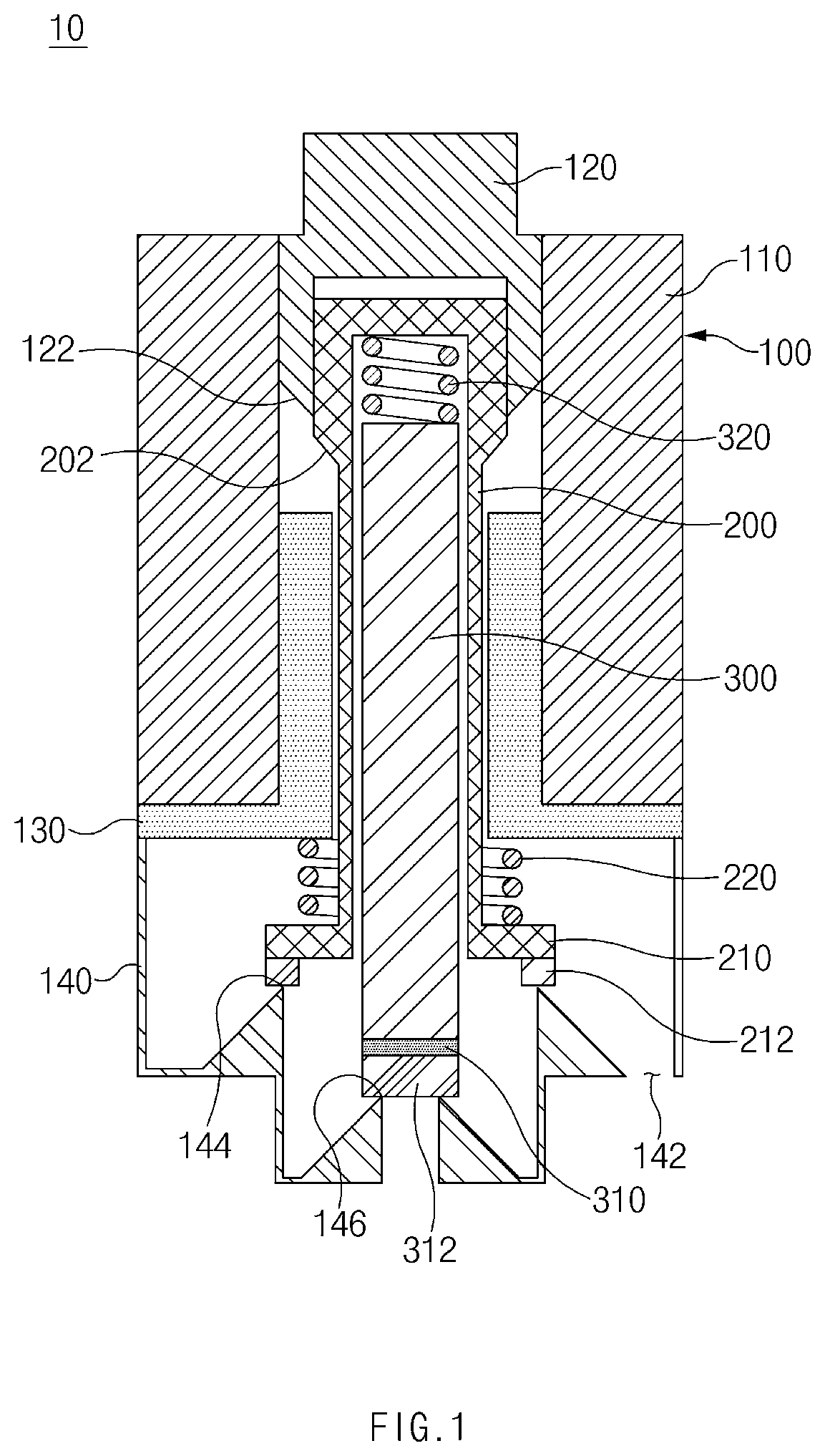
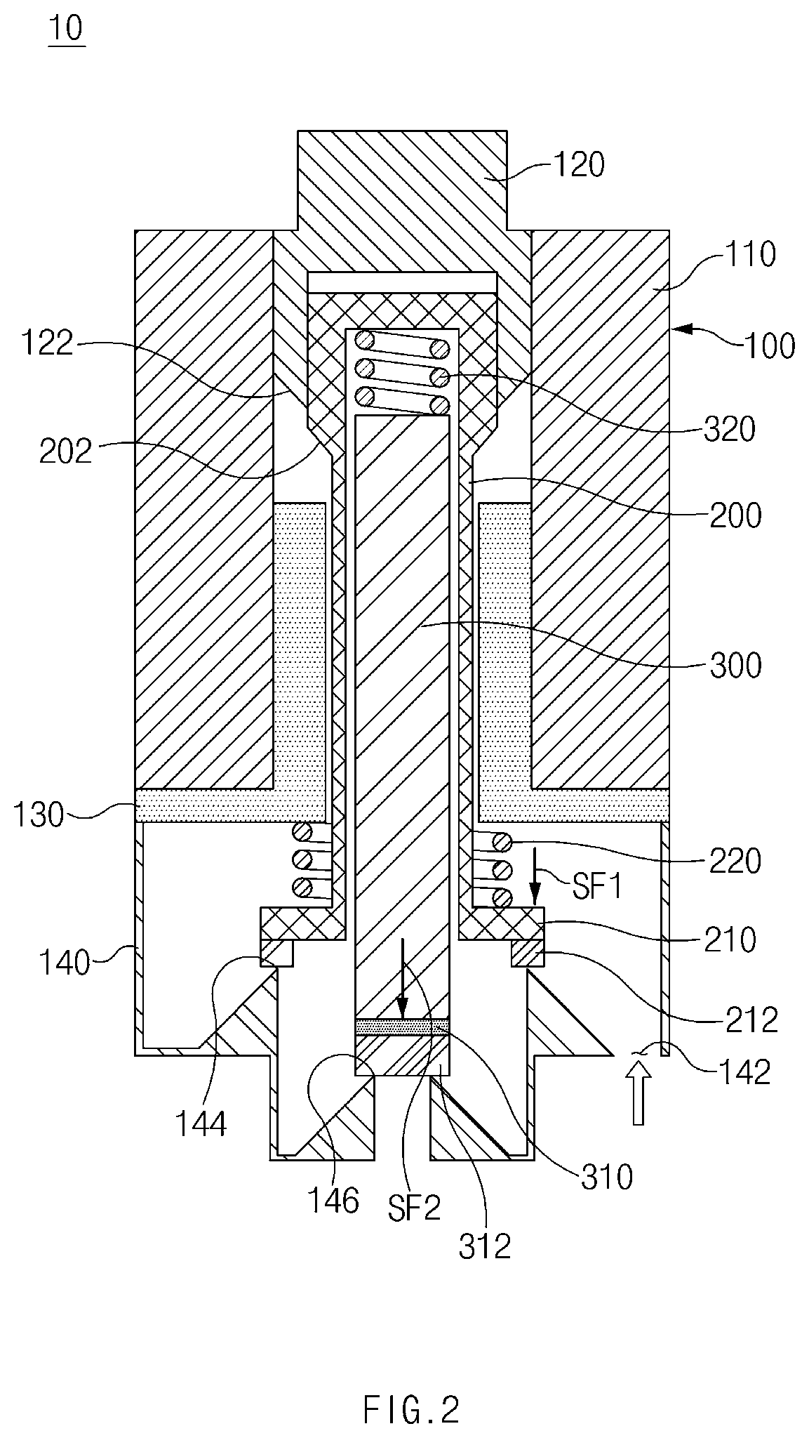
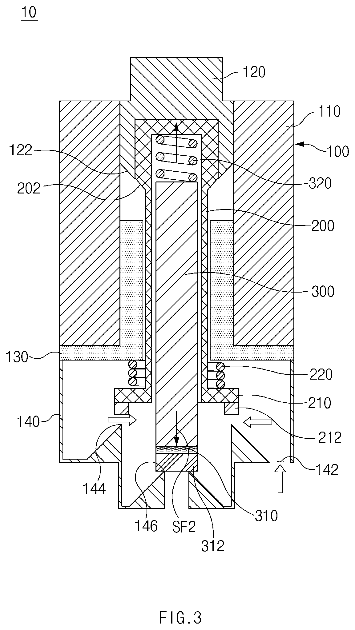
A solenoid valve including: a valve housing; a solenoid; a first plunger configured to be selectively moved rectilinearly by the solenoid; a first valve member connected to the first plunger and configured to selectively open or close a first outlet flow path in accordance with the movement of the first plunger; a first spring member configured to provide elastic force to move the first valve member to close the first outlet flow path; a second plunger provided to be rectilinearly movable in the first plunger and configured to be selectively moved rectilinearly by the solenoid; a second valve member connected to the second plunger and configured to selectively open or close a second outlet flow path in accordance with the movement of the second plunger; and a second spring member configured to provide elastic force to move the second valve member to close the second outlet flow path.

Description

CROSS-REFERENCE TO RELATED APPLICATION[0001]This application claims priority to and the benefit of Korean Patent Application No. 10-2020-0059398 filed in the Korean Intellectual Property Office on May 18, 2020, the entire contents of which are incorporated herein by reference.TECHNICAL FIELD[0002]The present disclosure relates to a solenoid valve, and more particularly, to a solenoid valve having ensured sealability and a simplified structure.BACKGROUND[0003]A solenoid valve may be used to regulate a flow of a fluid or control a pressure (flow rate) and the like.[0004]For example, the solenoid valve may be installed in a power train including an engine of a vehicle and serve to regulate a flow of a fluid such as fuel or oil or control a pressure. More specifically, a solenoid valve mounted in a fuel system may control an operation of supplying and injecting fuel, a solenoid valve mounted in a cooling system may control circulation for lubrication and cooling, and a solenoid valve mo...

Claims


Application Information

Patent Timeline
Patent Type & Authority Applications(United States)
IPC IPC(8): F16K1/44F16K31/06
CPCF16K1/443F16K31/0655F16K31/0675F16K11/02F02M51/061F02M61/06F02M61/1886F16K27/029F16K15/025F16K1/46
Inventor PARK, IN TAE
Owner HYUNDAI MOTOR CO LTD
Learn More