
Marine composite riser for structural health monitoring using piezoelectricity

a composite riser and structural health technology, applied in the oil and gas industry, can solve the problems of bending stress and strain along the riser pipe string, unstable riser system, etc., and achieve the effect of ensuring stability, ensuring stability, and spotting a relatively small or relatively large area

Inactive Publication Date: 2014-08-12
VETCO GRAY
View PDF11 Cites 4 Cited by
  • Summary
  • Abstract
  • Description
  • Claims
  • Application Information

AI Technical Summary

Benefits of technology

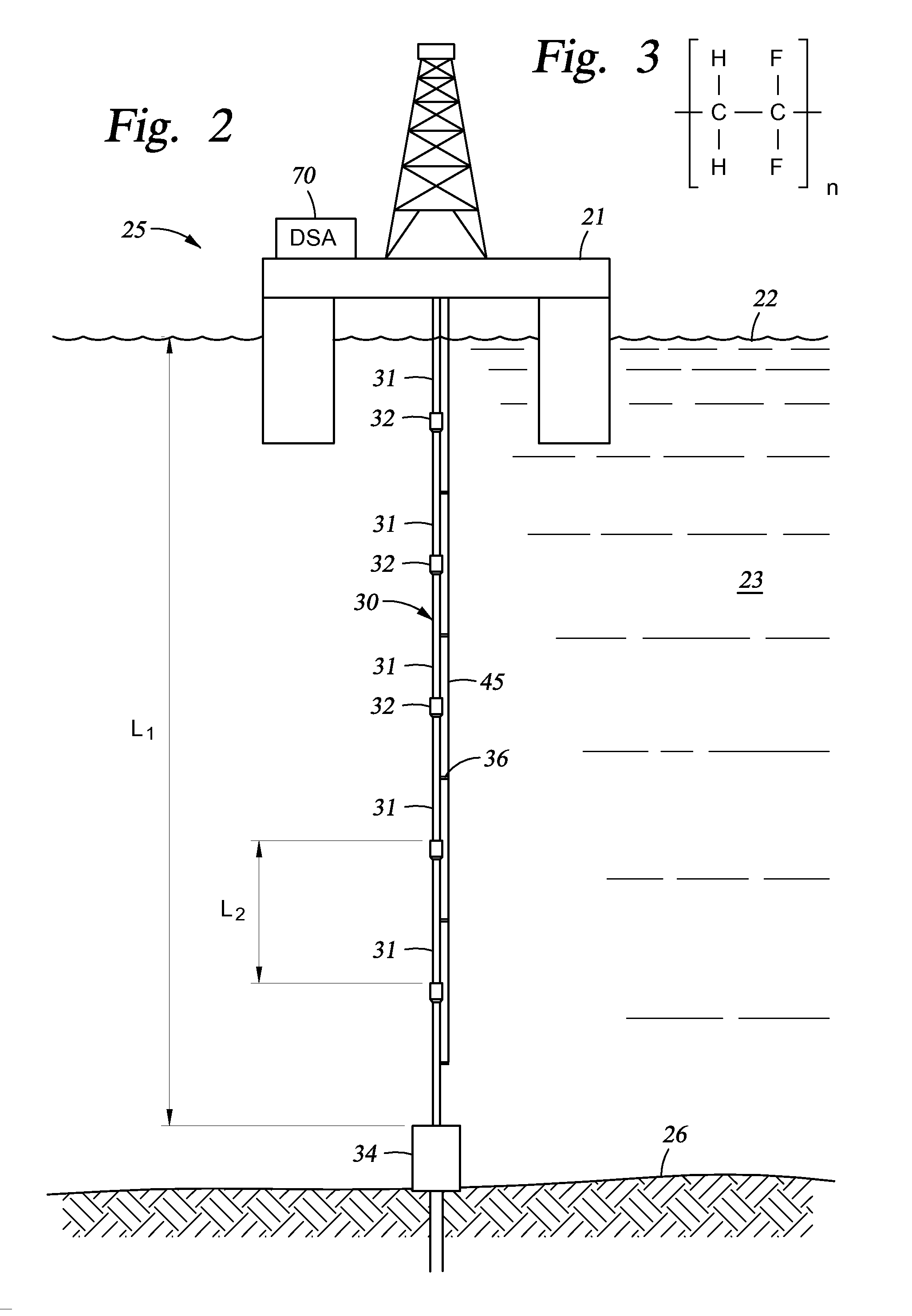
[0013]In view of the foregoing, Applicant recognizes that structural health monitoring techniques based on piezoelectricity offer portable, light-weight, low-powered, and inexpensive (both the equipment and to implement) solutions that can scan a relatively small or relatively large area quickly. Applicant further recognizes that a marine riser system provides a continuous source of bending and tensile stresses and strains. Typically, a riser is kept in tension using tensioners at the surface to keep the entire structure stable. A riser subjected to compression can buckle, resulting in an unstable riser system. Also, riser movement due to vessel offset or platform shift causes bending stresses and strains along the riser pipe string. Moreover, Applicant recognizes that PolyVinyliDene Fluoride (PVDF) laminates or films can be utilized by marine riser systems for active structural health monitoring of and subsea power generation. PVDF is a semi-crystalline polymer consisting of long chain of molecules with CH2-CF2 as a repeating unit. Specifically, Applicant recognizes that PVDF laminates or films can be embedded in and substantially circumscribe a riser composite pipe, constructing a vibration-based strain sensor, so that electricity is generated at the electrodes of the sensor responsive to mechanical stresses and strains of the marine riser pipe section. Advantageously, such laminate embodiments provide an enhanced ability to detect cracks in the composite riser (and not simply to provide stress and strain detection). Applicant recognizes that substantial amount of power can be generated from bonded or embedded PVDF laminates due to the piezoelectric effect. In addition, Applicant recognizes the need for systems, apparatuses and related methods using piezoelectricity for active structural health monitoring and subsea power generation in a marine riser system, including improved crack detection.
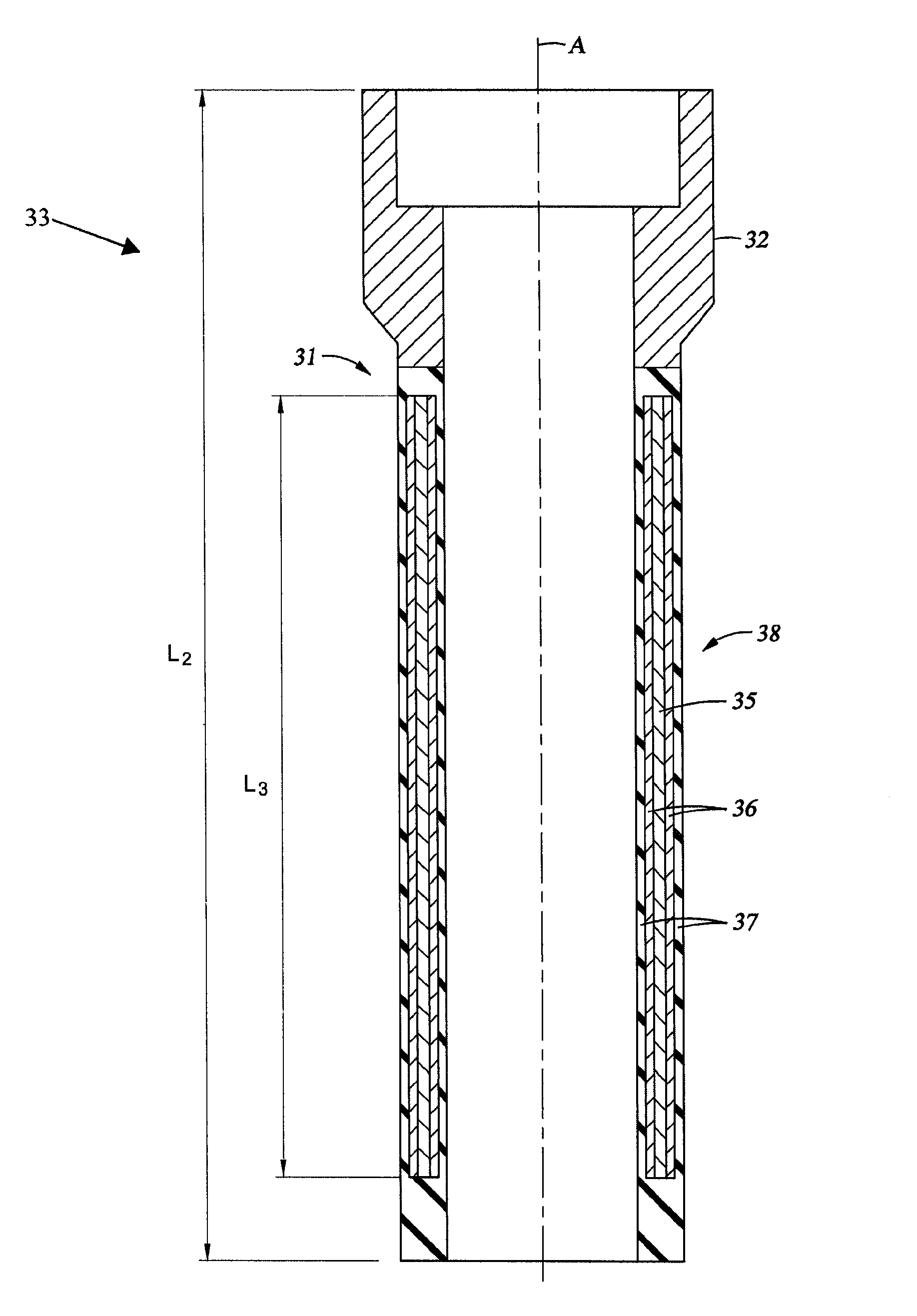
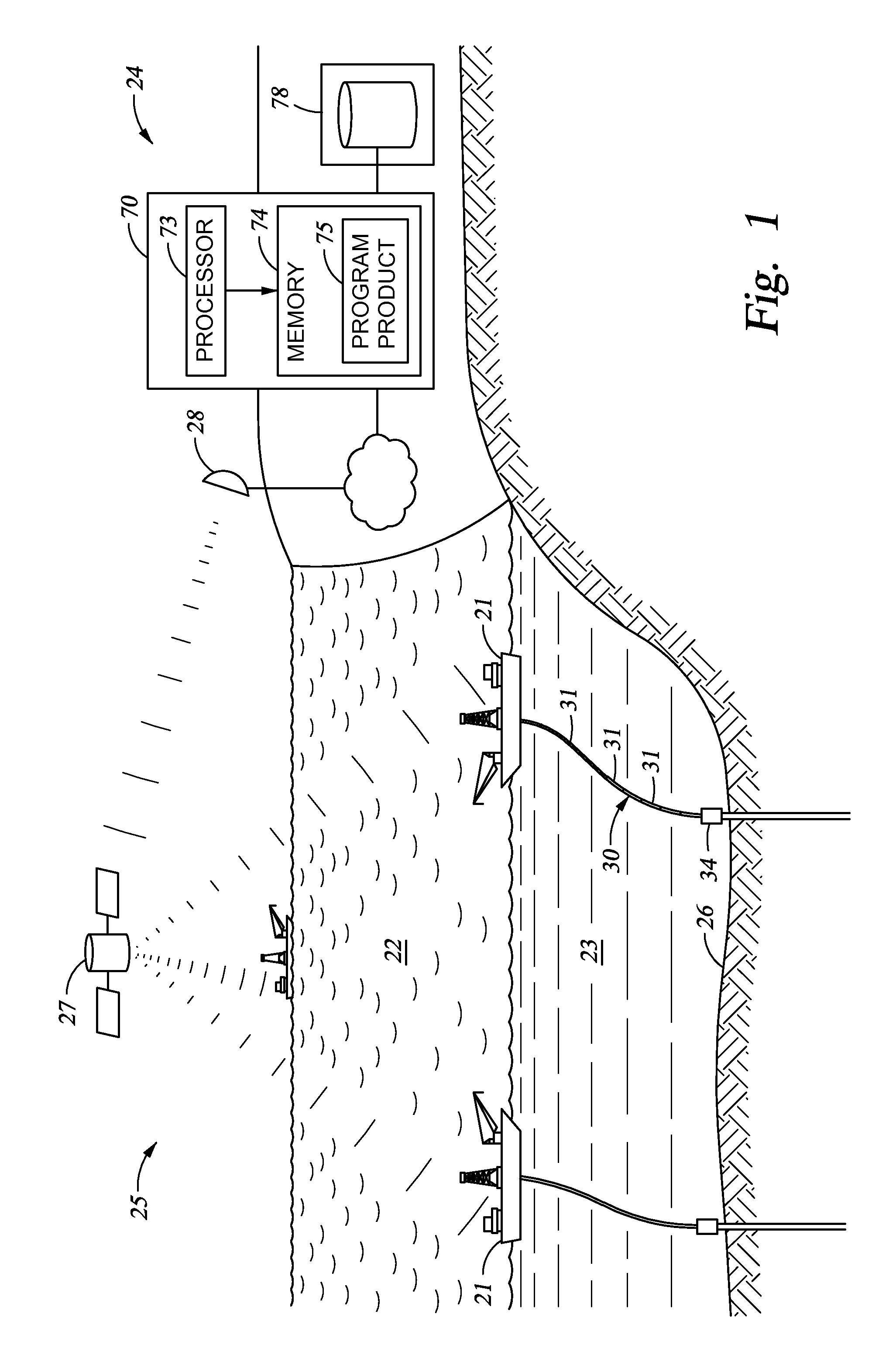
[0014]Embodiments of the present invention include, for example, a structural health monitoring system for a riser string. The system can include a marine riser pipe string. The marine riser pipe string can include a plurality of riser pipe sections and a plurality of riser connectors. Each of the plurality of riser pipe sections can include a cylindrical form having an axis, a carbon epoxy matrix, and a sensor. The sensor can include electrodes and a PolyVinyliDene Fluoride (PVDF) laminate substantially circumscribing the riser pipe section, thus providing enhanced riser crack detection over smaller piezoelectric sensors (with a lesser footprint). The sensor can be constructed to generate electricity at the electrodes responsive to mechanical stresses and strains of the riser pipe section. The system can further include a data acquisition system and a digital signal analyzer, e.g., located at the surface, to capture, digitize, and analyze electrical signals responsive to the generated electricity at the electrodes of sensors for the plurality of riser pipe sections and to provide health monitoring for the marine riser pipe string.

Problems solved by technology

A riser subjected to compression can buckle, resulting in an unstable riser system.
Also, riser movement due to vessel offset or platform shift causes bending stresses and strains along the riser pipe string.

Method used


Image

  • Marine composite riser for structural health monitoring using piezoelectricity
  • Marine composite riser for structural health monitoring using piezoelectricity
  • Marine composite riser for structural health monitoring using piezoelectricity

Examples


Embodiment Construction

[0028]The present invention will now be described more fully hereinafter with reference to the accompanying drawings, which illustrate embodiments of the invention. This invention may, however, be embodied in many different forms and should not be construed as limited to the illustrated embodiments set forth herein. Rather, these embodiments are provided so that this disclosure will be thorough and complete, and will fully convey the scope of the invention to those skilled in the art.

[0029]The embodiments of the present invention contribute to the usefulness of structural health monitoring of a marine riser systems in preventing oil leaks, spills, and associated effects on the environment. By detecting damage, e.g., cracks due to cyclic stress, riser sections may be replaced or repaired prior to failure or significant damage.

[0030]Applicant recognizes that structural health monitoring techniques based on piezoelectricity offer portable, light-weight, self-powered, and inexpensive (b...


PUM


Abstract

A structural health monitoring system for a marine composite riser string is provided. Each riser pipe section includes a cylindrical form having an axis and also a carbon epoxy matrix. A sensor is associated with (e.g., embedded in) and substantially circumscribes the riser pipe section. The sensor includes a PolyVinyliDene Fluoride laminate and electrodes (e.g., conductive silver ink coating) so that the sensor generates electricity at the electrodes responsive to mechanical stresses and strains of the riser section, including vibrations. The system can also include a data acquisition system and digital signal analyzer to analyze signals responsive to the generated electricity at the electrodes of sensors and to provide health monitoring and damage detection for the marine riser pipe string, including impact damage and fatigue crack initiation. The system can further include a subsurface energy storage device and a plurality subsurface microelectromechanical devices coupled to the subsurface energy storage device.

Description

BACKGROUND OF THE INVENTION[0001]1. Field of the Invention[0002]The present invention relates to the oil and gas industry. More particularly, the present invention relates to active structural health monitoring of marine composite riser systems in a production phase.[0003]2. Description of Related Art[0004]In the oil and gas industry, a riser is a string of pipe between the surface and sea bottom. Oil and gas riser pipe strings are assembled sequentially and connect a surface ship, rig, or platform to subsea equipment, including, for example, a Christmas tree, blow out preventer (BOP), or lower marine riser package (LMRP), as understood by those skilled in the art.[0005]During a typical field installation at sea, marine riser pipes are individually lifted from the deck of a vessel, connected to each other at the riser spider, and run down. Two riser pipes are joined, or coupled, by means of a mechanical connector. The length between two riser couplings varies typically between 40 to...

Claims


Application Information

Patent Timeline
Patent Type & Authority Patents(United States)
IPC IPC(8): G01V1/00E21B17/01
CPCE21B17/01E21B47/0006E21B47/007G01M5/0058G01M5/0083
Inventor PHADKE, ASHUTOSH, CHANDRASHEKHAR
Owner VETCO GRAY
Learn More