
Blocked valve isolation tool

a technology of blocked valves and isolation tools, which is applied in the direction of diaphragm valves, boring/drilling equipment, pipe elements, etc., can solve the problems of inconvenient or dangerous gas leakage of the system, inconvenient and expensive, and affecting the operation of the system, and achieving substantial downtime and expens

Active Publication Date: 2014-08-12
SAUDI ARABIAN OIL CO
View PDF11 Cites 6 Cited by
  • Summary
  • Abstract
  • Description
  • Claims
  • Application Information

AI Technical Summary

Benefits of technology

The patent is about a way to temporarily block gas flow in a duct to prevent leaks or potential leaks. This is done by inserting an inflatable element that closes off the duct. Overall, the patent describes a method and device for controlling gas flow in a duct to prevent leaks.

Problems solved by technology

Removal of a valve may expose the system to inconvenient or dangerous leakage of gas from the duct upstream of the removed valve particularly where a blocking valve does not achieve 100% shut-off.
A common but usually inconvenient and expensive solution to this leakage problem is to shut down the parent system or at least to shut down the subsystem in the immediate vicinity of the relief valve to be removed.
In a large gas treatment or production plant there are a great many such relief valves that need periodic attention as described above, or need removal in emergency situations, costing substantial downtime and expense.

Method used


Image

  • Blocked valve isolation tool
  • Blocked valve isolation tool
  • Blocked valve isolation tool

Examples


first embodiment

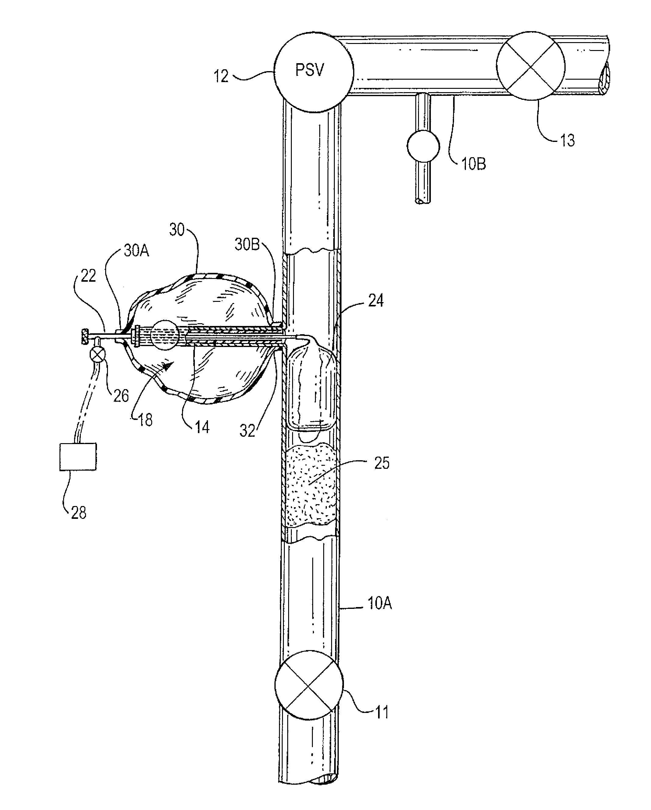
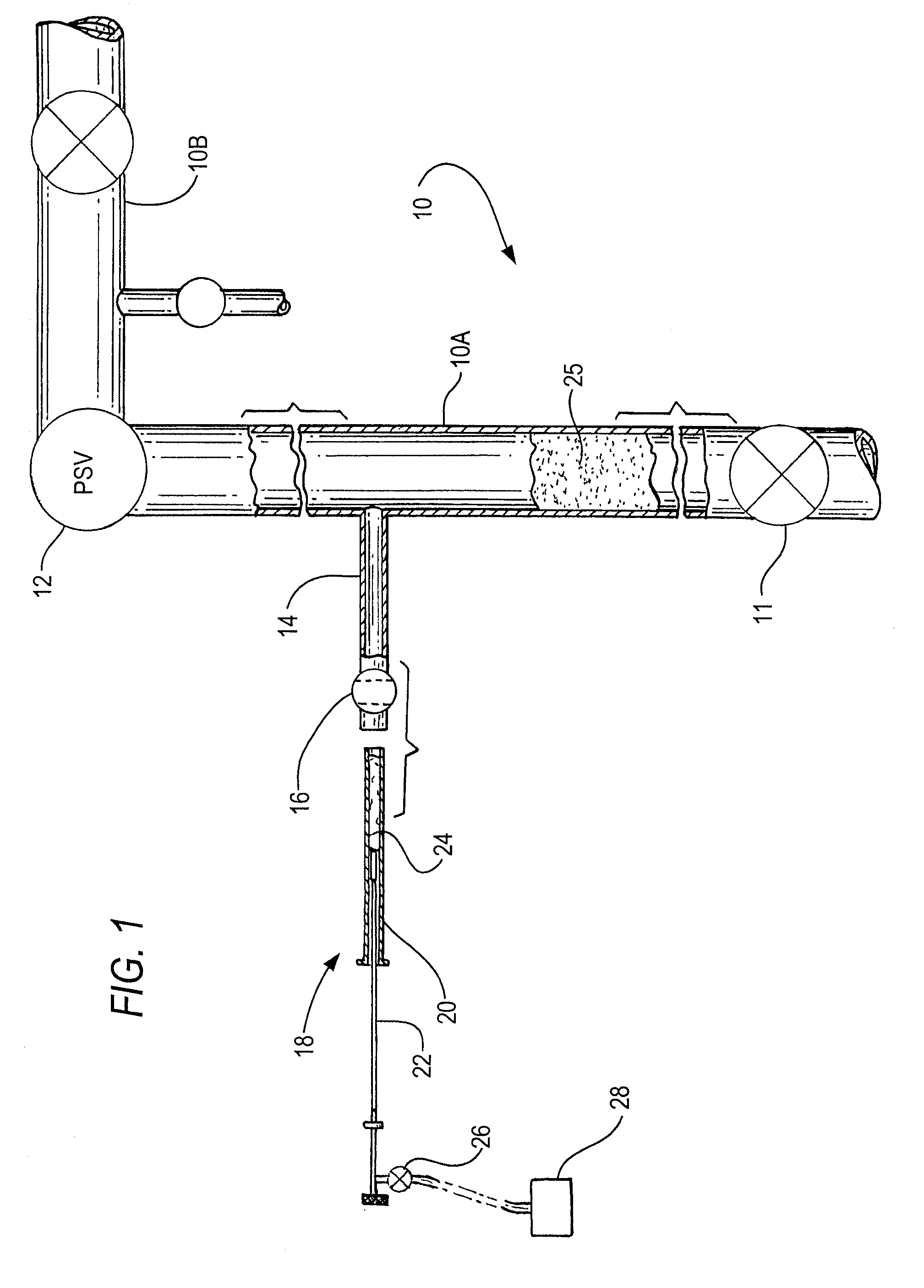
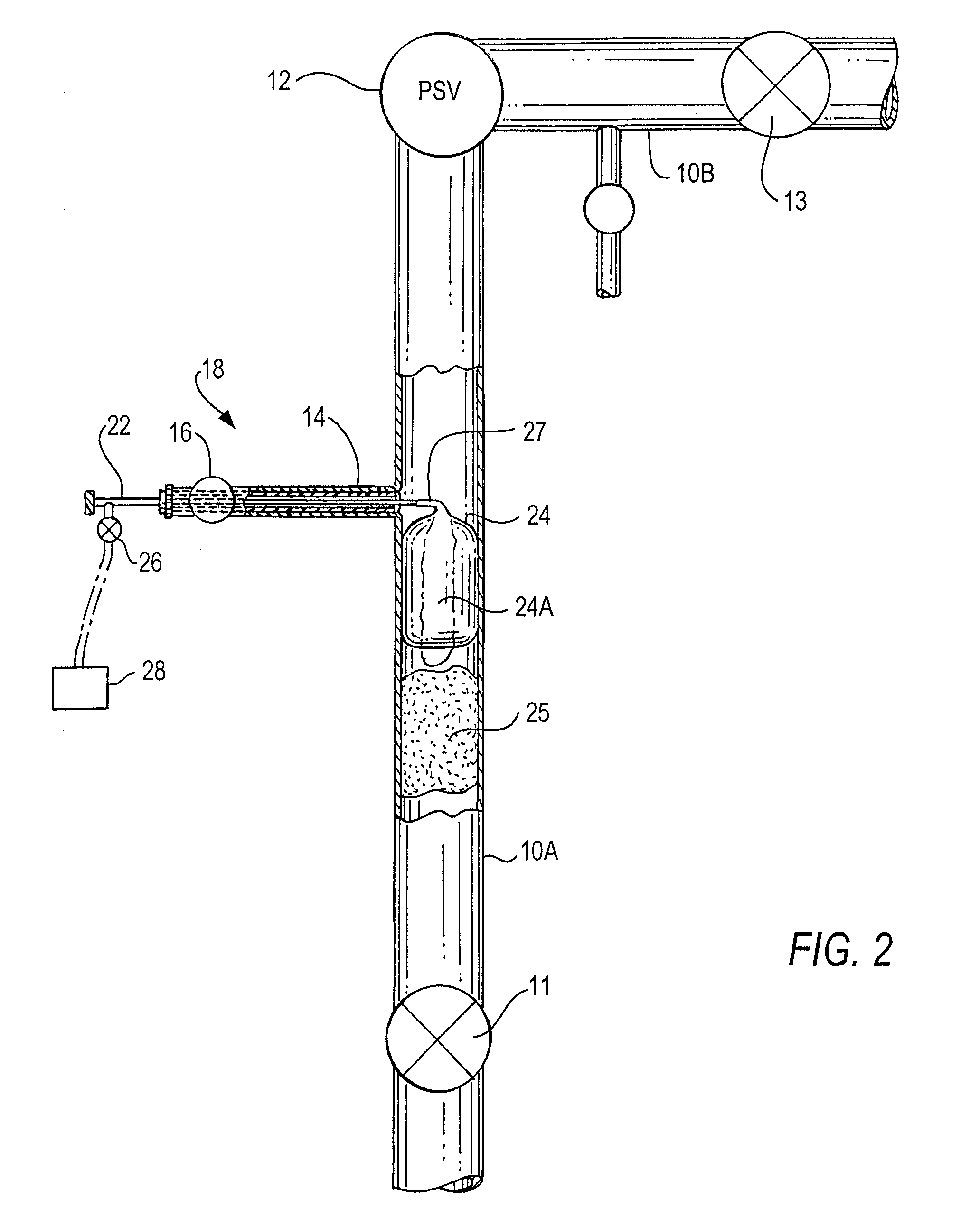
[0032]FIGS. 1 through 3 illustrate the present invention as a device operable in a duct system through which flows a gas that should be prevented from escaping while a downstream valve is inspected, removed, repaired and / or replaced. The relevant duct system includes an upstream duct 10A, relief valve 12 and further duct 10B downstream of relief valve 12. A gas flows through this duct 10A-10B with relief valve 12 in line to monitor pressure of the gas flow and relieve excessive pressure if such occurs; however, periodically the relief valve needs to be isolated, inspected and as required removed, repaired or replaced and re-installed. A principal object of this invention is to allow an efficient inspection, repair and / or replacement of a relief valve without having to shut down significant portions of the system, particularly the duct 10A-10B where the relief valve is located.

[0033]As seen in FIGS. 1 and 2, extending transversely out of duct 10A, is vent duct 14, blocking valve (on / ...

second embodiment

[0043]FIGS. 4 and 5 illustrate the new invention which has the features of the embodiment of FIGS. 1-3 plus a rubber cover 30 designed to create a gas seal about valve isolation tool 18, so that gas which leaks or flows through blocking valve 11 cannot escape out through duct 14 and / or through valve 16 or other parts of isolation tool 18.

[0044]FIG. 4 shows cover 30 as a balloon-like element encompassing the proximal part of isolation tool 18, with the cover's proximal end 30A secured about the near end of inner tube 22 and its distal end 30B (shown stretched open for clarification) encompassing part of outer tube 20. FIG. 5 shows isolation tool 18 fully inserted through duct 14, and the distal end 30B of cover 30 secured about the near end of duct 14. FIG. 5 illustrates how cover 30 blocks escape of any gas that flows or leaks past valve 11 into duct 14, or flows upstream from relief valve 12 and into and through duct 14 and into components of isolation tool 18. The cover's distal e...


PUM


Abstract

A leaking block valve isolation tool for insertion through a vent duct and blocking valve of a gas flow duct. The isolation tool includes an outer tube having proximal and distal ends, the outer tube having a diameter sized to extend through the vent duct and blocking valve. An inner tube having proximal and distal ends is arranged coaxially with and movable within the outer tube. An inflatable balloon is attached to the distal end of the inner tube, wherein the isolation tool outer tube is insertable through the vent duct to an opening in the gas flow duct. The inner tube is slidably insertable through the outer tube until the balloon is situated within a bore formed through the gas flow duct and is inflatable therein to block any gas leak through the gas flow duct.

Description

I. CROSS-REFERENCE TO RELATED APPLICATION[0001]This patent application claims the benefit of U.S. Provisional Application No. 61 / 567,387, filed Dec. 6, 2011, the content of which is incorporated by reference herein in its entirety.II. FIELD OF THE INVENTION[0002]This invention is in the field of gas treatment and production facilities, and particularly procedures employed in a portion of a gas flow duct system for isolation and removal of a valve for inspection, repair or replacement.III. BACKGROUND OF THE INVENTION AND PRIOR ART[0003]In facilities for processing, storing and distributing gaseous products there are numerous relief valves for monitoring, controlling and relieving pressure build-up of gas flowing in duct systems. From time to time such relief valves need to be inspected and removed and replaced. Removal of a valve may expose the system to inconvenient or dangerous leakage of gas from the duct upstream of the removed valve particularly where a blocking valve does not a...

Claims


Application Information

Patent Timeline
Patent Type & Authority Patents(United States)
IPC IPC(8): F16L55/12F16L55/124F16K7/10F16L55/134
CPCF16L55/124F16L55/134F16K7/10Y10T137/598Y10T137/0475
Inventor AL, SHAMMARY, MOHAMMAD, AHMED
Owner SAUDI ARABIAN OIL CO
Learn More