Method for manufacturing a multimode optical fibre
a manufacturing method and optical fiber technology, applied in the field of multimode optical fibers having refractive index profiles, to achieve the effects of less wavelength dependence, high bandwidth, and precise refractive index profiles
- Summary
- Abstract
- Description
- Claims
- Application Information
AI Technical Summary
Benefits of technology
Problems solved by technology
Method used
Image

Examples
example 1
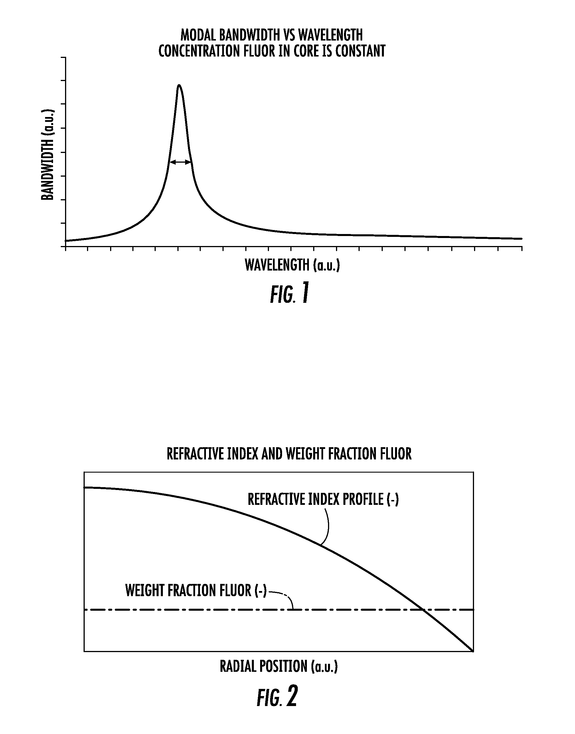
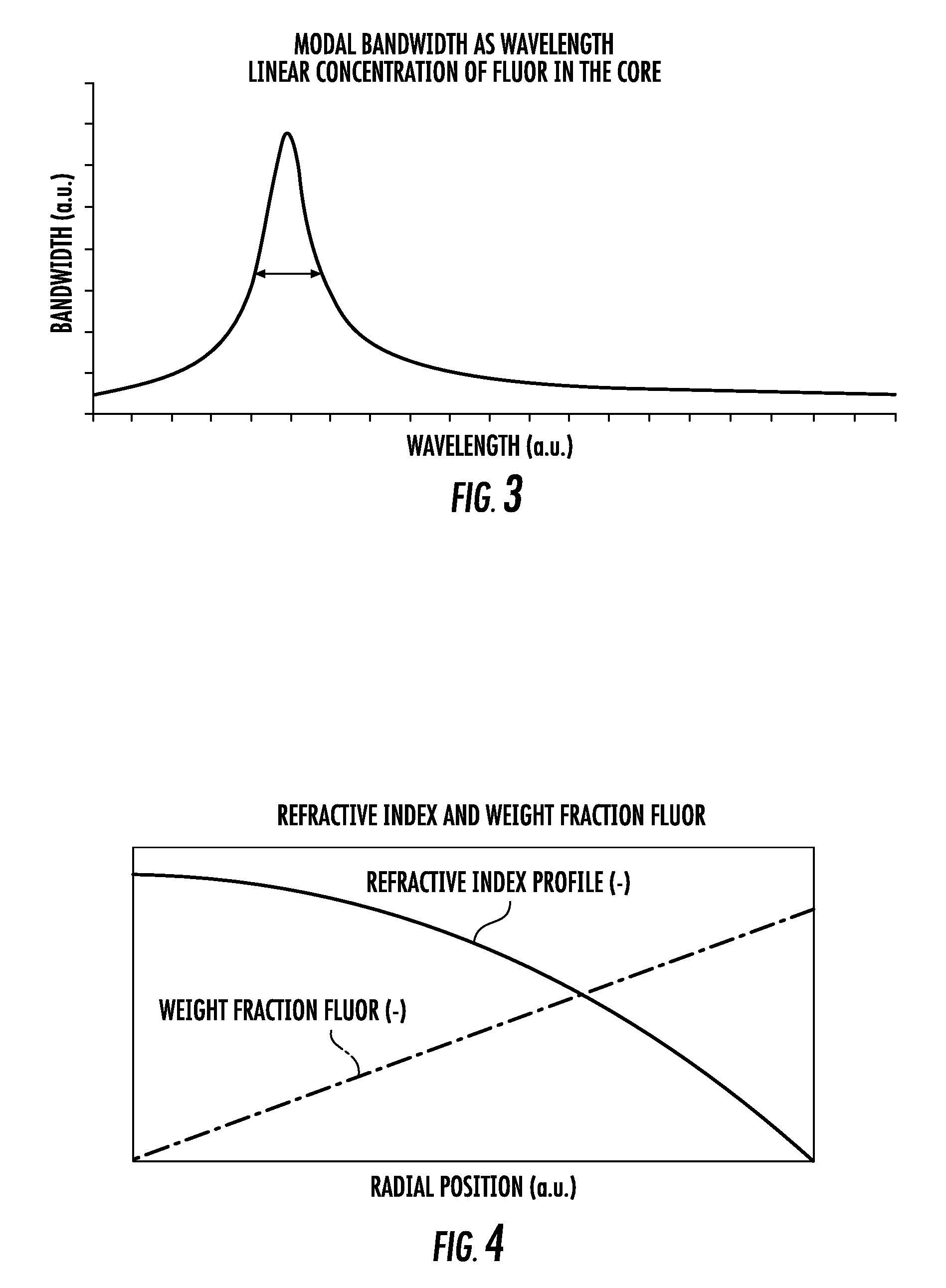
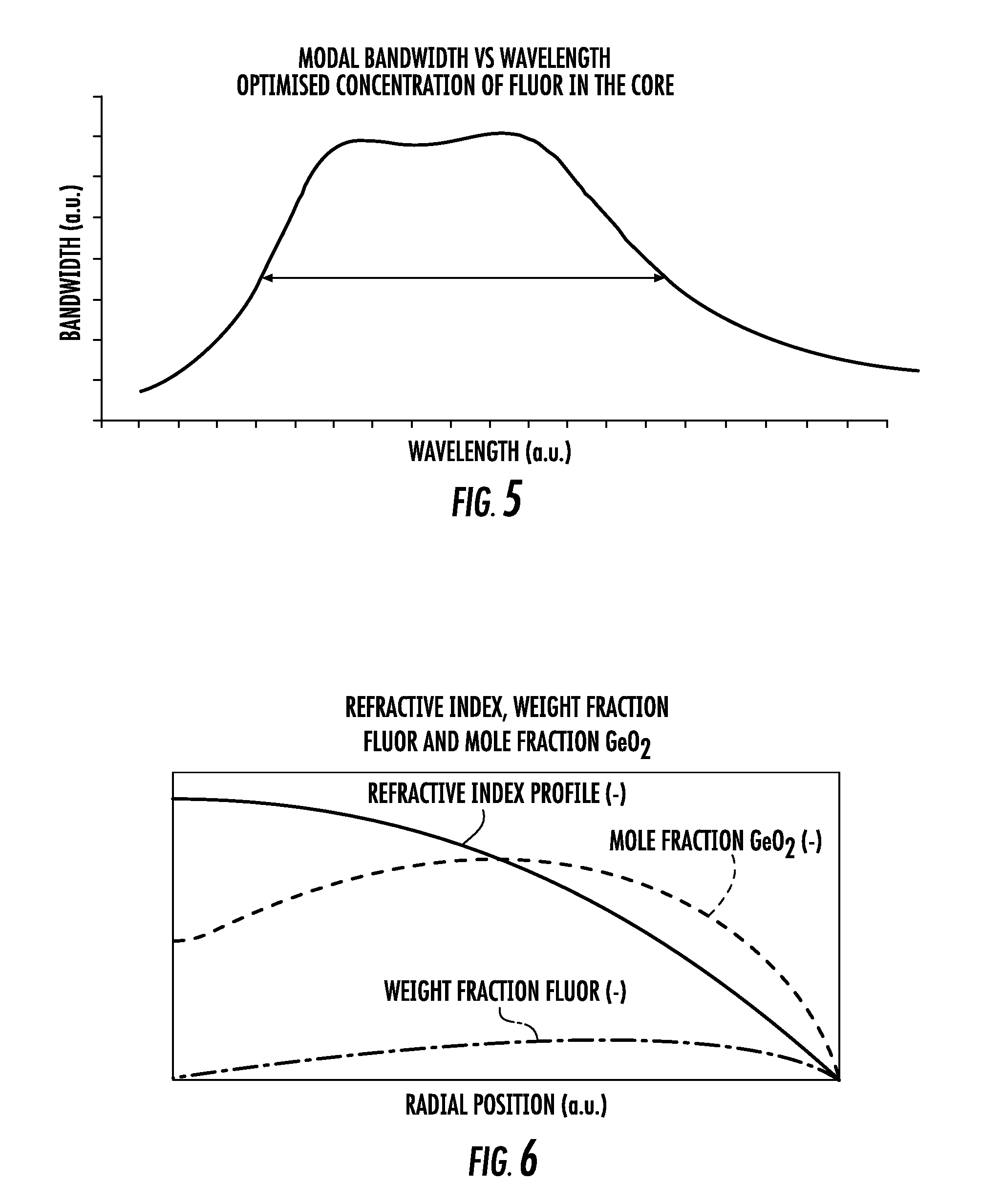
[0053]A multimode optical fibre comprising a core having a gradient index of refraction in accordance with equation 1, a core diameter of 50.2 μm and an NA of 0.201 was formed. The value of the profile shape parameter a was 1.97. The concentration of fluorine (F) in the core increased from 0 weight percent on the central fibre axis, at r=0, to 4 weight percent at the edge of the core, at r=a.
[0054]The bandwidth of said fibre was measured at 850 nm and at a number of wavelengths around 1300 nm, using the method of FOTP-204. The results are presented in the Table 1 (below). Furthermore, the DMD was measured at 1300 nm, the DMD pulse responses did not exhibit any perturbations in the central part.
[0055]
TABLE 1Wavelength l [nm]85012501270130013301350Bandwidth [MHz · km]44720371979228020271829
[0056]In the illustrated wavelength range around 1300 nm, a minimum bandwidth of 1821 Mhz·km over the entire wavelength range is required in order to be able to guarantee a transmission rate of at l...
example 2
[0065]A multimode optical fibre comprising a core having a gradient index of refraction in accordance with equation 1, a core diameter of 62.3 μm and an NA of 0.269 was formed. The value of the profile shape parameter α was 1.97. The concentration of fluorine (F) in the core increased from 0 weight percent on the central fibre axis, at r=0, to 4 weight percent at the edge of the core, at r=a.
[0066]The bandwidth of said fibre was measured at a wavelength of 850 nm and at a number of wavelengths around 1300 nm, using the method of FOTP-204. The results are presented in the Table 4 (below). Furthermore, the DMD was measured at 1300 nm, the DMD pulse responses did not exhibit any perturbations in the central part.
[0067]
TABLE 4Wavelength l [nm]85012501270130013301350Bandwidth [MHz · km]1757208201010904817
[0068]In the illustrated wavelength range around 1300 nm, a minimum bandwidth of 707 Mhz·km over the entire wavelength range is required in order to be able to guarantee a transmission r...
example 3
[0073]A multimode optical fibre comprising a core having a gradient index of refraction in accordance with equation 1, a core diameter of 49.7 μm and an NA of 0.198 was formed. The value of the profile shape parameter α was 2.045. The concentration of fluorine (F) in the core increased from 0 weight percent on the central fibre axis, at r=0, to 2 weight percent at the edge of the core, at r=a.
[0074]The bandwidth of said fibre was measured at a number of wavelengths around 850 nm and at 1300 nm, using the method of FOTP-204. The results are presented in the Table 6 (below). Furthermore, the DMD was measured at 850 nm, the DMD pulse responses did not exhibit any perturbations in the central part.
[0075]
TABLE 6Wavelength l [nm]8008208508759001300Bandwidth [MHz · km]21822604488027912081634
[0076]In the illustrated wavelength range around 850 nm, a minimum bandwidth of 2000 Mhz·km over the entire wavelength range is required in order to be able to guarantee a transmission rate of 10 Gbit / s...
PUM
| Property | Measurement | Unit |
|---|---|---|
| wavelength bandwidth | aaaaa | aaaaa |
| wavelength bandwidth | aaaaa | aaaaa |
| length | aaaaa | aaaaa |
Abstract
Description
Claims
Application Information
 - R&D
- Intellectual Property
- Life Sciences
- Materials
- Tech Scout
- Unparalleled Data Quality
- Higher Quality Content
- 60% Fewer Hallucinations
Browse by: Latest US Patents, China's latest patents, Technical Efficacy Thesaurus, Application Domain, Technology Topic, Popular Technical Reports.
© 2025 PatSnap. All rights reserved.Legal|Privacy policy|Modern Slavery Act Transparency Statement|Sitemap|About US| Contact US: help@patsnap.com