
Noise parameter measurement system and method

a noise parameter and measurement system technology, applied in the field of noise parameter measurement system and method, can solve the problems of difficult identification and elimination, measurement errors and uncertainties, and extremely sensitive noise measurements

Inactive Publication Date: 2014-07-22
TSIRONIS CHRISTOS
View PDF4 Cites 21 Cited by
  • Summary
  • Abstract
  • Description
  • Claims
  • Application Information

AI Technical Summary

Benefits of technology

The invention is about a method for testing and characterizing microwave and RF transistors and amplifiers. The method uses automatic microwave tuners to synthesize reflection factors and collect data using high sensitivity receivers. The method measures the purity of the signal entering and existing at the input and output ports of the DUT using the noise figure (NF) at each frequency and bias condition. The invention is about extracting the four noise parameters of the DUT using a test setup and data acquisition and processing method. The technical effect of the invention is to provide a reliable and accurate way to characterize the noise behavior of microwave and RF transistors and amplifiers.

Problems solved by technology

However, noise measurements are extremely sensitive and various disturbances cause measurement errors and uncertainties.
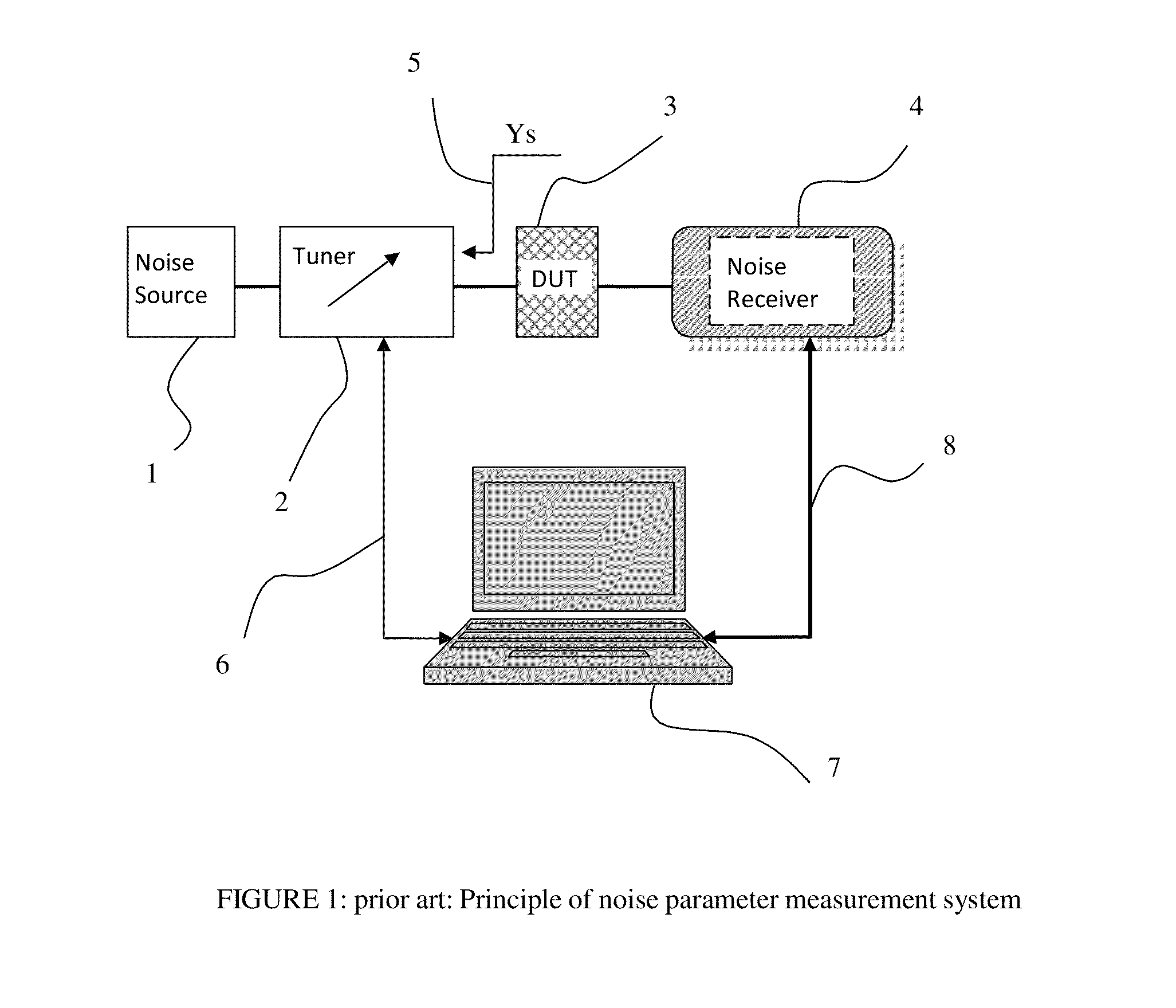
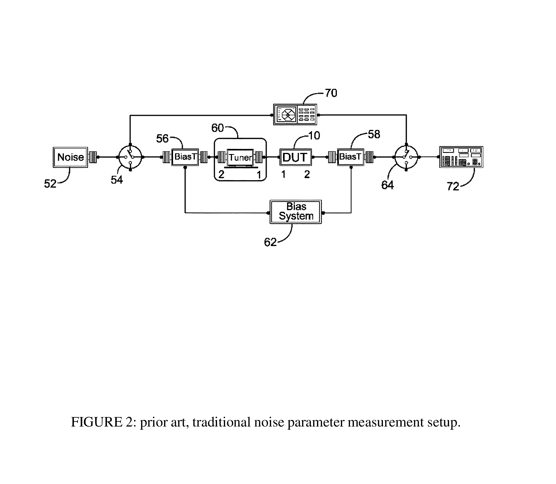
This method has been used and refined for many years ([5], FIGS. 2, 3 and [6]) but is in general cumbersome and prone to insufficiencies, since the DUT may oscillate or the impedance tuner may create measurement errors, which are difficult to identify and eliminate if there are not enough data points to extract from.
This is done in order to increase the measurement speed, at the risk of measurement accuracy.
However it is impossible to optimize the tuning pattern for each parameter setting, as Simpson attempts: for each frequency the same tuner probe / slug position corresponds to different source admittance and for each other DC bias point the optimum area of source admittance is different, since the parameters of the DUT change with DC bias.
Simpson, however, does not disclose any data cleaning and filtering criteria, beyond an algorithm for optimizing the distribution of tuner settings, which in end-effect is ineffective.

Method used


Image

  • Noise parameter measurement system and method
  • Noise parameter measurement system and method
  • Noise parameter measurement system and method

Examples


Embodiment Construction

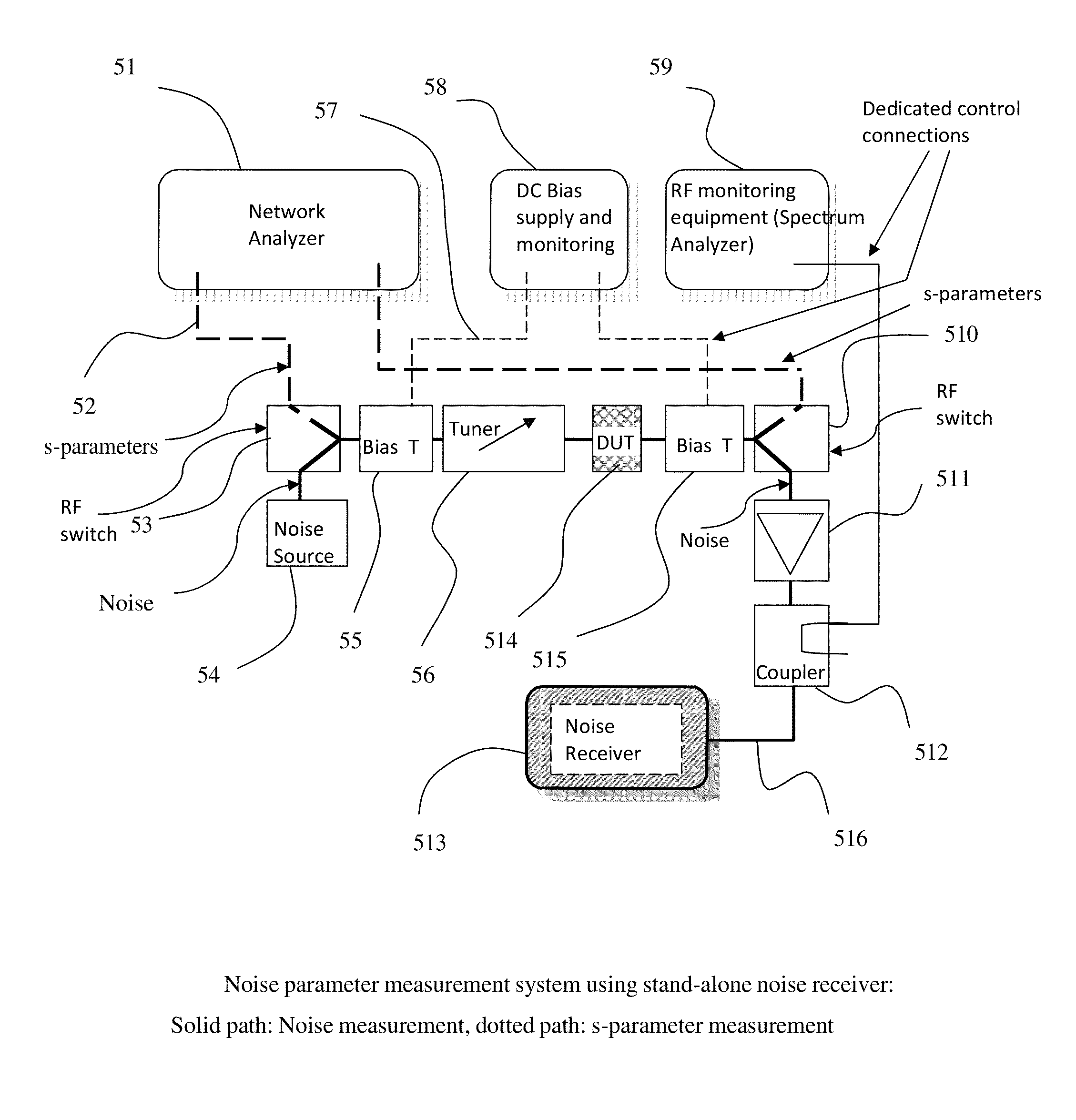
[0040]The method described here can be employed with three different test setups depending on the available test equipment (FIGS. 5, 6 and 7). In FIG. 5 a network analyzer (51) is included, as a separate unit from the noise receiver (513) and can be switched on to the DUT (514), path (52) using switches (53) and (510) in order to measure the S-parameters of the DUT. In this case the tuner (56) is initialized (=full transmission line) and the two bias tees (55) and (515) are part of a previous calibration, which allows de-embedding the S-parameters and correcting to the DUT reference plane [10]. The receiver (513) is preceded by a low noise amplifier (511) which increases the sensitivity of the measurement and a directional coupler (512) which allows connecting to a spectrum analyzer (59) for detecting spurious oscillations but also spurious interfering signals from outside. The power supply (58) is also monitored by the control computer, in order to detect bias instabilities during ...


PUM


Abstract

A wideband four noise parameter measurement system and method uses electro-mechanical wideband tuners and fast noise and small signal receivers (network analyzers) to collect noise data in fast frequency sweeps over a large number of randomly distributed source tuner states; because of the random nature of source impedances, additional monitoring equipment allow evaluating critical device parameters in view of output mismatch and instabilities in order to validate the measured data. Multiple noise parameter extractions for all possible cross-combinations of source impedance states at each measured frequency allows reliable and physically meaningful generation of wideband noise parameters, even for very low noise and potentially unstable DUT's.

Description

PRIORITY CLAIM[0001]Not ApplicableCROSS-REFERENCE TO RELATED ARTICLES[0002][1] H. ROTHE and W. DAHLKE, “Theory of noisy four poles”, Proceedings of the IRE, June 1956, pages 811-818.[0003][2]“Friis formulas for noise”, http: / / en.wikipedia.org / wiki / Friis_formulas_for_noise[0004][3] SISCHKA, Franz, “Basics of S-parameters, part 1”, Characterization handbook, March 2002.[0005][4]“Understanding Noise Parameter Basics / Understanding Noise Parameter Measurements”, Application Note AN60-040, http: / / www.modelithics.com / literature.asp.[0006][5] SIMPSON, G. “Data measurement methods and systems”, U.S. Provisional patent application US 2010 / 0030504 A1.[0007][6] M. SANNINO, “On the determination of Device Noise and Gain Parameters”, Proceedings IEEE, vol. 67, pages 1364-1382, September 1979.[0008][7] R. LANE, “The determination of Device Noise Parameters”, Proceedings IEEE, vol. 57, pages 1461-1462, August 1969.[0009][8] Patent DE 41 22 189 (1268-P).[0010][9]“Noise Figure Measurement Accuracy—Th...

Claims


Application Information

Patent Timeline
Patent Type & Authority Patents(United States)
IPC IPC(8): G01R27/06
CPCG01R31/2626G01R29/26G01R27/06
Inventor TSIRONIS, CHRISTOS
Owner TSIRONIS CHRISTOS
Learn More