Device for the generation of aerodynamic vortices and also a regulating flap and wing with a device for the generation of aerodynamic vortices

a technology of aerodynamic vortices and regulating flaps, which is applied in the direction of influencers using rotating members, airflow influencers, transportation and packaging, etc., can solve the problems of reducing the life and circumferential velocity of the vortex, and achieve the effect of low resource requirements, minimal separation of aircraft at the airport, and increased lift and take-off and landing tim

Active Publication Date: 2014-07-22
AIRBUS OPERATIONS GMBH
View PDF29 Cites 5 Cited by
  • Summary
  • Abstract
  • Description
  • Claims
  • Application Information

AI Technical Summary

Benefits of technology

This patent is about a device that generates aerodynamic vortices on the side edge of a main wing or regulating flap to increase the lift of an aircraft during take-off and landing. The device includes a bundle of tip vortices that form a vortex coil and dissipate quickly, reducing resistance and increasing the ratio of lift to resistance. This allows for a minimum separation between aircraft and improves the control of gusts and flight dynamics. The device can be easily integrated with existing aircraft designs and requires minimal resources.

Problems solved by technology

The decomposition of the previous central tip vortex into a vortex coil reduces the life and circumferential velocity of the vortex as a result of increased dissipation.

Method used


Image

  • Device for the generation of aerodynamic vortices and also a regulating flap and wing with a device for the generation of aerodynamic vortices
  • Device for the generation of aerodynamic vortices and also a regulating flap and wing with a device for the generation of aerodynamic vortices
  • Device for the generation of aerodynamic vortices and also a regulating flap and wing with a device for the generation of aerodynamic vortices

Examples


Embodiment Construction

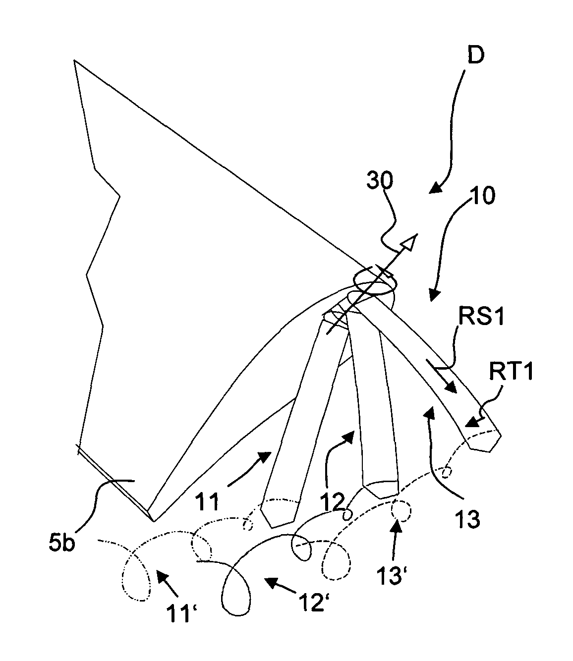
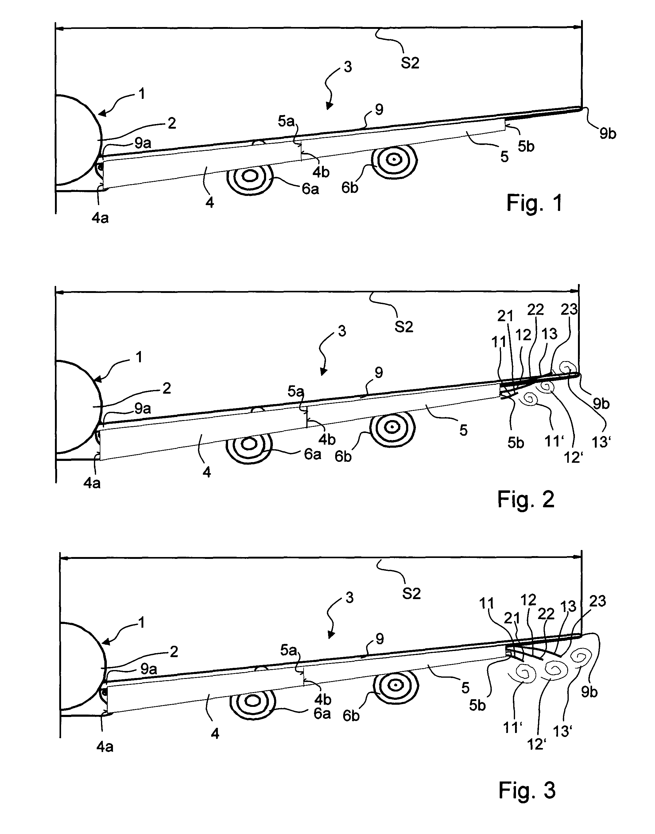
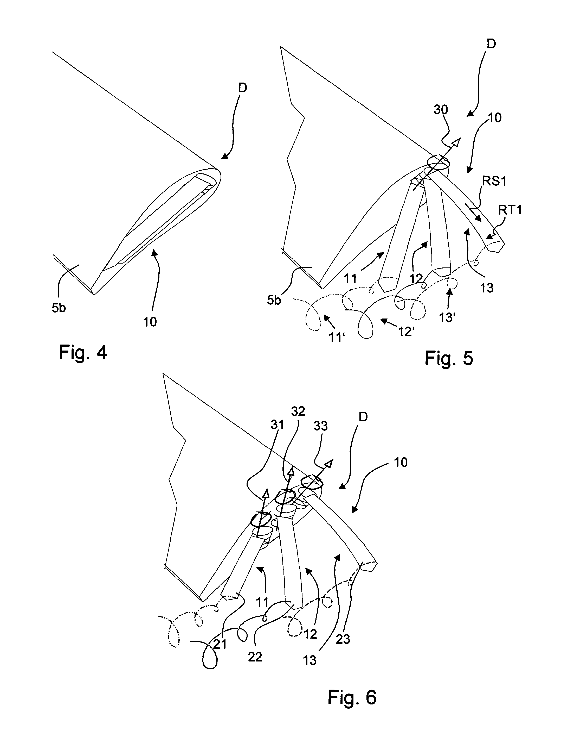
[0046]FIG. 1 shows an aircraft 1 with a fuselage 2 and a wing 3 as seen from the rear and in the direction of flight, or along the longitudinal axis of the aircraft. In this viewing direction the right-hand of the two wings of the aircraft is thus shown with the half span width S2. On the main wing 9 of the wing 3 as shown are represented an inner 4 and an outer 5 high-lift flap,in each case in its extended state, and also two engine nacelles 6a, 6b. The inner and the outer high-lift flap 4, 5 have in each case an inner end 4a and 5a respectively, facing towards the fuselage 2 and an outer end 4b, 5b respectively, facing away from the fuselage 2, or facing towards the wing tip. Likewise the main wing 9 has an outer end 9b, situated opposite to the fuselage-side end 9a of the main wing 9. In this context the term “end” is used for the spanwise side edge of the contour of the high-lift flap 4, 5, or of the main wing 9, respectively.

[0047]In accordance with the invention a device 10 fo...


PUM


Abstract

A device for the generation of aerodynamic vortices to be arranged on the spanwise side edge of a wing, or a regulating flap adjustably arranged on the latter, which in each case have a chordwise direction and a spanwise direction, wherein the device is formed from one aerofoil component or from a plurality of aerofoil components, wherein the at least one aerofoil component is designed as a part that can be moved relative to the wing or regulating flap in its spanwise direction, wherein the device for vortex generation has an actuation device for the retraction and extension of the aerofoil components into a recess, and also a drive device to operate the actuation device. A regulating flap of a wing, and also a wing, with such a device for the generation of aerodynamic vortices, and a wing, which has at least two aerofoil segments at its side edge situated at the spanwise end.

Description

CROSS REFERENCE TO RELATED APPLICATIONS[0001]This application claims priority to PCT Application No. PCT / EP2009 / 004207, file Jun. 10, 2009; which claims priority to German Patent Application No. DE 102008027618.9, filed Jun. 10, 2008, and claims the benefit to U.S. Provisional Application No. 61 / 060,210, filed Jun. 10, 2008, the entire disclosures of which applications are hereby incorporated by reference.BACKGROUND[0002]The invention concerns a device for the generation of aerodynamic vortices and also a regulating flap and wing with a device for the generation of aerodynamic vortices.[0003]Modern commercial aircraft have high-lift aids in order to generate the necessary lift at low speeds during the take-off and landing phases. From the general prior art it is of known art that aerodynamic lifting surfaces such as high-lift systems (high-lift devices) and main and auxiliary aerofoil devices are fitted with wing tips that are cut off straight, or rounded, or with so-called winglets...

Claims


Application Information

Patent Timeline
Patent Type & Authority Patents(United States)
IPC IPC(8): B64C9/34B64C9/06B64C9/08B64C23/06
CPCB64C23/065Y02T50/164B64C23/076Y02T50/10
Inventor SCHABER, SVEN
Owner AIRBUS OPERATIONS GMBH
Why Eureka
Try Eureka