
Well tool with shearable collet

a technology of collet and running tool, which is applied in the direction of drilling casings, drilling pipes, and accessories for wells, etc., can solve the problems of limiting the length of the liner, the length of the drilled hole, and the inability to retrieve components, so as to limit the axial movement

Active Publication Date: 2014-07-22
SCHLUMBERGER TECH CORP
View PDF10 Cites 7 Cited by
  • Summary
  • Abstract
  • Description
  • Claims
  • Application Information

AI Technical Summary

Benefits of technology

Enables the precise disengagement of the collet from the liner hanger, allowing for the retrieval and re-run of bottom hole assemblies, thereby extending drilling depth and enabling the use of directional steering tools and logging instruments without removing the entire liner string.

Problems solved by technology

However, the liner does not extend back to the wellhead assembly at the surface.
This technique does not allow one to employ components that must be retrieved, which might include downhole steering tools, measuring while drilling instruments and retrievable drill bits.
Being unable to retrieve the bit for replacement thus limits the length that can be drilled and thus the length of the liner.
If unable to retrieve and rerun the bottom hole assembly, the operator would not be able to liner drill with expensive directional steering tools, logging instruments and the like, without planning for removing the entire liner string to retrieve the tools.
If the operator wishes to retrieve the bottom hole assembly before cementing the liner, there are no established methods and equipment for doing so.
Also, if the operator wishes to rerun the bottom hole assembly and continue drilling with the liner, there are no established methods and equipment for doing so.
One difficulty to overcome in order to retrieve and rerun a bottom hole assembly during liner drilling concerns how to keep the liner from buckling if it is disconnected from the drill pipe and left in the well.
But, there is a risk that the liner might buckle due to inadequate strength to support its weight in compression.
While feasible, controlling the force at which the collet releases from the set liner hanger is difficult.

Method used


Image

  • Well tool with shearable collet
  • Well tool with shearable collet
  • Well tool with shearable collet

Examples


second embodiment

[0053]A second embodiment is illustrated in FIGS. 14-16. Liner hanger control tool 103 is the same as liner hanger control tool 47 of FIG. 2 and releasable connects to a liner hanger 104 that is the same as liner hanger 25 of FIG. 7. An outer housing 105 of liner hanger control tool 103 encloses a mandrel 107, which connects into a drill pipe string such as drill pipe string 37 (FIG. 2). A passage 109 extends through mandrel 107 and the drill pipe string. An external sleeve 111 is secured by threads to outer housing 105 and extends into the upper end of liner hanger housing 113. Slips 115 are movable carried within windows in liner hanger housing 113.

[0054]A collet cage 117 having collet windows 119 is movable and supports a collet 121. Collet cage 117 is the same as collet cage 83 (FIG. 6). Collet 121 has fingers 123 attached to flexible depending bands, which bias fingers 123 radially outward. Fingers 123 may be located within collet windows 119. Collet 121 is constructed the same...

first embodiment

[0056]The embodiment of FIGS. 14-16 operates in the same manner as the first embodiment, differing only in the location of shear pins 127. As mentioned, FIG. 14 shows the run-in and drilling position. The weight of the drill string and liner string below mandrel 107 is supported by mandrel 107, not by collet 121. When liner hanger control tool 103 sets liner hanger 104, it will appear as in FIG. 15, with shear pin 127 still unsheared. Liner control tool outer housing 105, along with external sleeve 111, collet cage 117 and collet 121 have moved upward in unison relative to mandrel 107. Liner hanger housing 113, which is attached to the upper end of the liner string, remains stationary. This movement causes collet fingers 123 to lift slips 115, which forces them radially outward to the set position of FIG. 15. Then, slacking weight off the drill pipe string will cause slips 115 to grip the casing, supporting the weight of the liner string.

[0057]Continued upward force is applied on sh...


PUM


Abstract

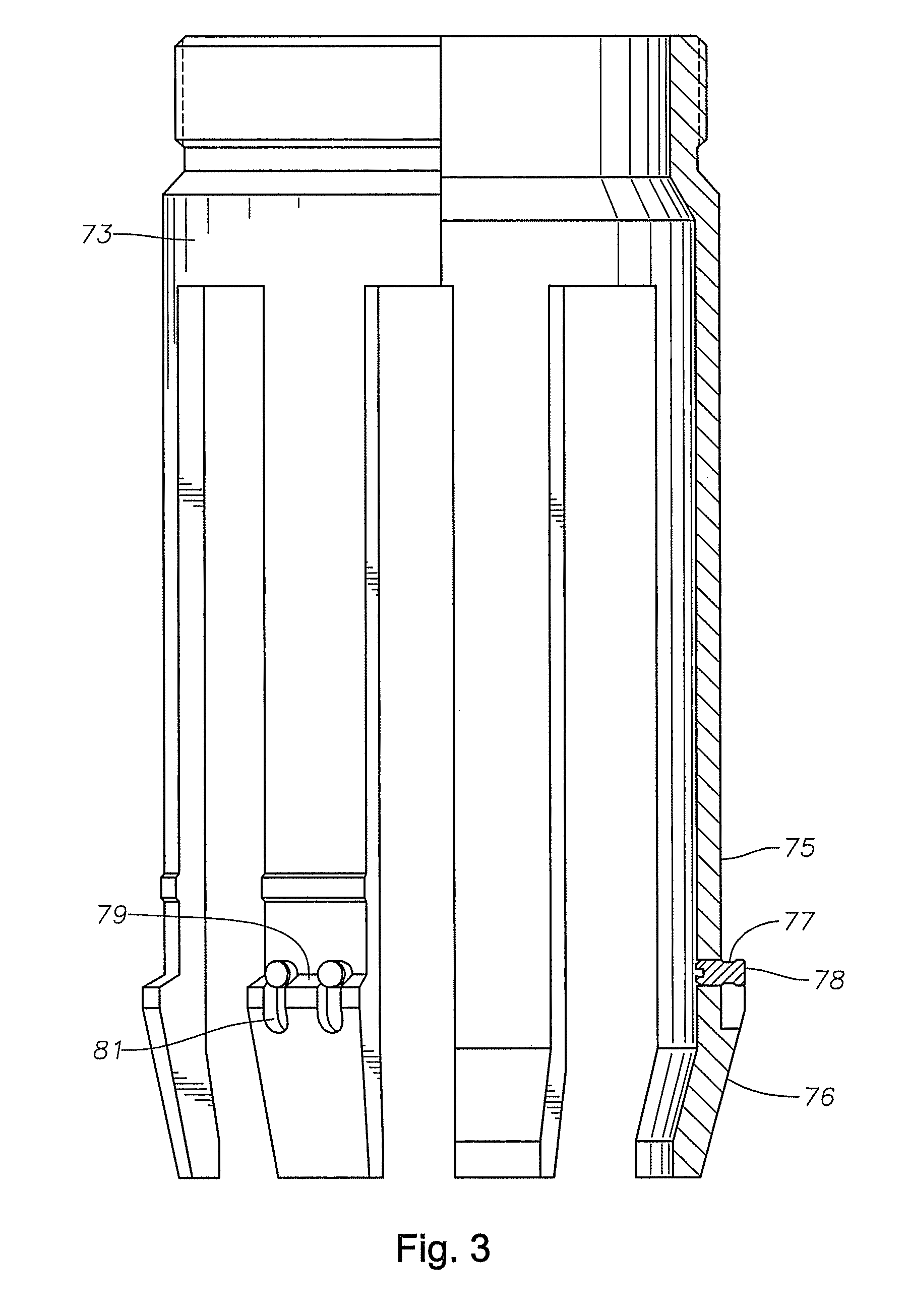
A running tool for well drilling operations is carried by a running string into and out of a wellbore. A collet is carried by the running tool, the collet having fingers with a radially expanded position arranged to latch against a wellbore shoulder in the wellbore. The fingers are resiliently and radially contractible. A shear element is carried by the collet, the shear element preventing the fingers from radially contracting to unlatch the running tool while the shear element is intact. If a selected axial force is applied against the shear element, it shears, freeing the collet fingers to retract. The collet may be part of a tool to set and release a liner hanger from engagement with a string of casing.

Description

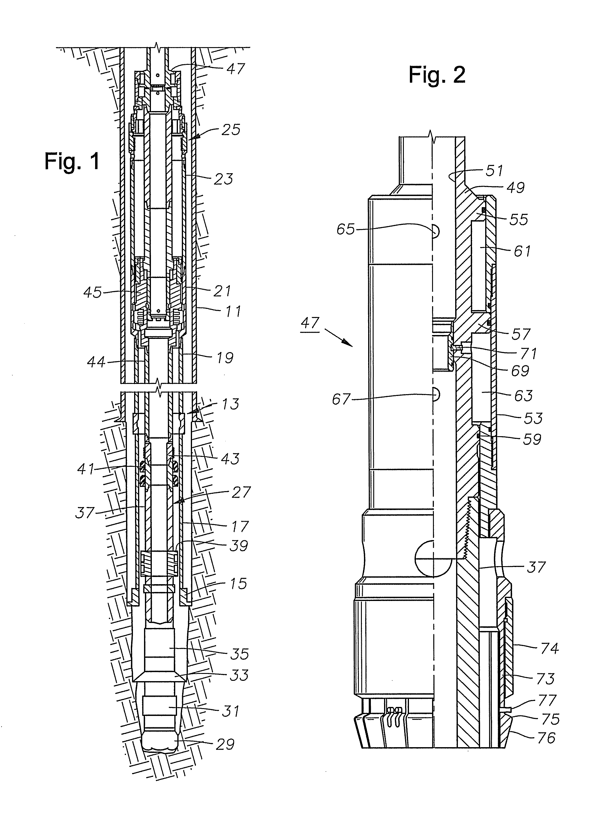
FIELD OF THE INVENTION[0001]This invention relates in general to oil and gas well drilling while simultaneously installing a liner in the well bore, and in particular to a running tool having a collet latch with shear elements to set a liner hanger.BACKGROUND OF THE INVENTION[0002]Oil and gas wells are conventionally drilled with drill pipe to a certain depth, then casing is run and cemented in the well. The operator may then drill the well to a greater depth with drill pipe and cement another string of casing. In this type of system, each string of casing extends to the surface wellhead assembly.[0003]In some well completions, an operator may install a liner rather than an inner string of casing. The liner is made up of joints of pipe in the same manner as casing. Also, the liner is normally cemented into the well. However, the liner does not extend back to the wellhead assembly at the surface. Instead, it is secured by a liner hanger to the last string of casing just above the low...

Claims


Application Information

Patent Timeline
Patent Type & Authority Patents(United States)
IPC IPC(8): E21B23/00
CPCE21B17/06E21B23/02E21B23/04
Inventor ERIKSEN, ERIK P.TATE, BARRY J.
Owner SCHLUMBERGER TECH CORP
Learn More