
Impact treatment method for improving fatigue characteristics of welded joint, impact treatment device for improving fatigue characteristics for same, and welded structure superior in fatigue resistance characteristics

a technology of impact treatment and welded joints, which is applied in the direction of heat treatment furnaces, heat treatment equipment, furnaces, etc., can solve the problems of difficult adoption and commercial utilization of welded joints, and achieve the effect of improving the fatigue characteristics of welded joints, and efficient transmission

Inactive Publication Date: 2014-07-15
NIPPON STEEL CORP
View PDF23 Cites 4 Cited by
  • Summary
  • Abstract
  • Description
  • Claims
  • Application Information

AI Technical Summary

Benefits of technology

This approach stabilizes and improves fatigue resistance by applying compressive residual stress over a larger area of the weld toe, reducing stress concentration and enhancing the fatigue life of welded joints, while also simplifying the treatment process and reducing costs through automation and efficient inspection.

Problems solved by technology

However, this ultrasonic impact treatment has been developed on the assumption that treatment will be performed manually, thus there has been cases where its adoption has been difficult such as in structures requiring continuous treatment over long distances such as in steel bridges and cranes and in factories and the like where assembly is becoming automated.
There have been cases where commercial utilization has been difficult from a cost perspective as well as a result.

Method used


Image

  • Impact treatment method for improving fatigue characteristics of welded joint, impact treatment device for improving fatigue characteristics for same, and welded structure superior in fatigue resistance characteristics
  • Impact treatment method for improving fatigue characteristics of welded joint, impact treatment device for improving fatigue characteristics for same, and welded structure superior in fatigue resistance characteristics
  • Impact treatment method for improving fatigue characteristics of welded joint, impact treatment device for improving fatigue characteristics for same, and welded structure superior in fatigue resistance characteristics

Examples


first embodiment

[0082]In the impact treatment device for improving fatigue characteristics 60 shown in FIG. 4 as the first embodiment, the treatment mechanism side is fixed to the device base 65, and a movement mechanism (not shown) carrying the treated material (welded joint) and sliding is provided on the device base 65. This movement mechanism may move the welded joint 10 in a state where the sliding direction and the longitudinal direction of the weld bead 20 are matched.

[0083]Further, the impact treatment device for improving fatigue characteristics 60 is provided with a treatment mechanism 61 positioned above this movement mechanism and fit with the impact pin 50 and a support pressing mechanism 62 to which this treatment mechanism 61 is attached. This support pressing mechanism 62 comprises a support arm 63 and a pressing device 64 and is fixed to the device base 65.

[0084]The treatment mechanism 61 presses the impact pin 50 against the surface of base metal material (steel plate 11 or 12) se...

second embodiment

[0091]The impact treatment device for improving fatigue characteristics 70 shown in FIG. 5 as the second embodiment is provided with a not shown device base. The welded joint 10 may be carried on this device base.

[0092]Further, the impact treatment device for improving fatigue characteristics 70 is provided with a treatment mechanism 71 positioned above this device base and fit with the impact pin 50, a support pressing mechanism 72 to which this treatment mechanism 71 is attached, and a movement mechanism 73 sliding this support pressing mechanism 72 in one direction.

[0093]The treatment mechanism 71 presses the impact pin 50 against the surface of the base metal material (steel plate 11 or 12) separated from the toe 20b of the weld bead 20 by a predetermined distance and applies hammer peening treatment or ultrasonic impact treatment. It may be ones disclosed in for example the Patent Literatures 1 to 3 and the like. Note that, hammer peening treatment and ultrasonic impact treatme...

examples

[0113]Below, examples will be used to make the advantageous effects of the present invention clearer. Note that, the present invention is not limited to the following examples and may be carried out with appropriate changes to the extent that the gist is not changed.


PUM

PropertyMeasurementUnit
thicknessaaaaaaaaaa
thicknessaaaaaaaaaa
thicknessaaaaaaaaaa

Abstract

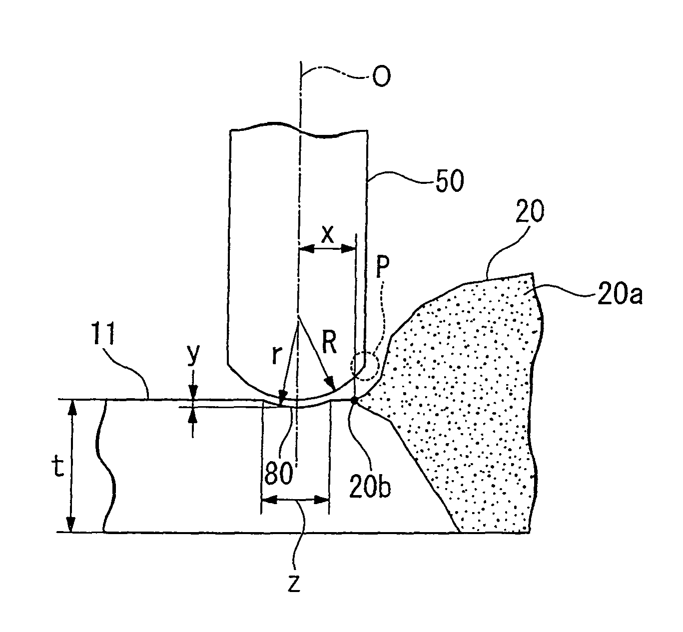
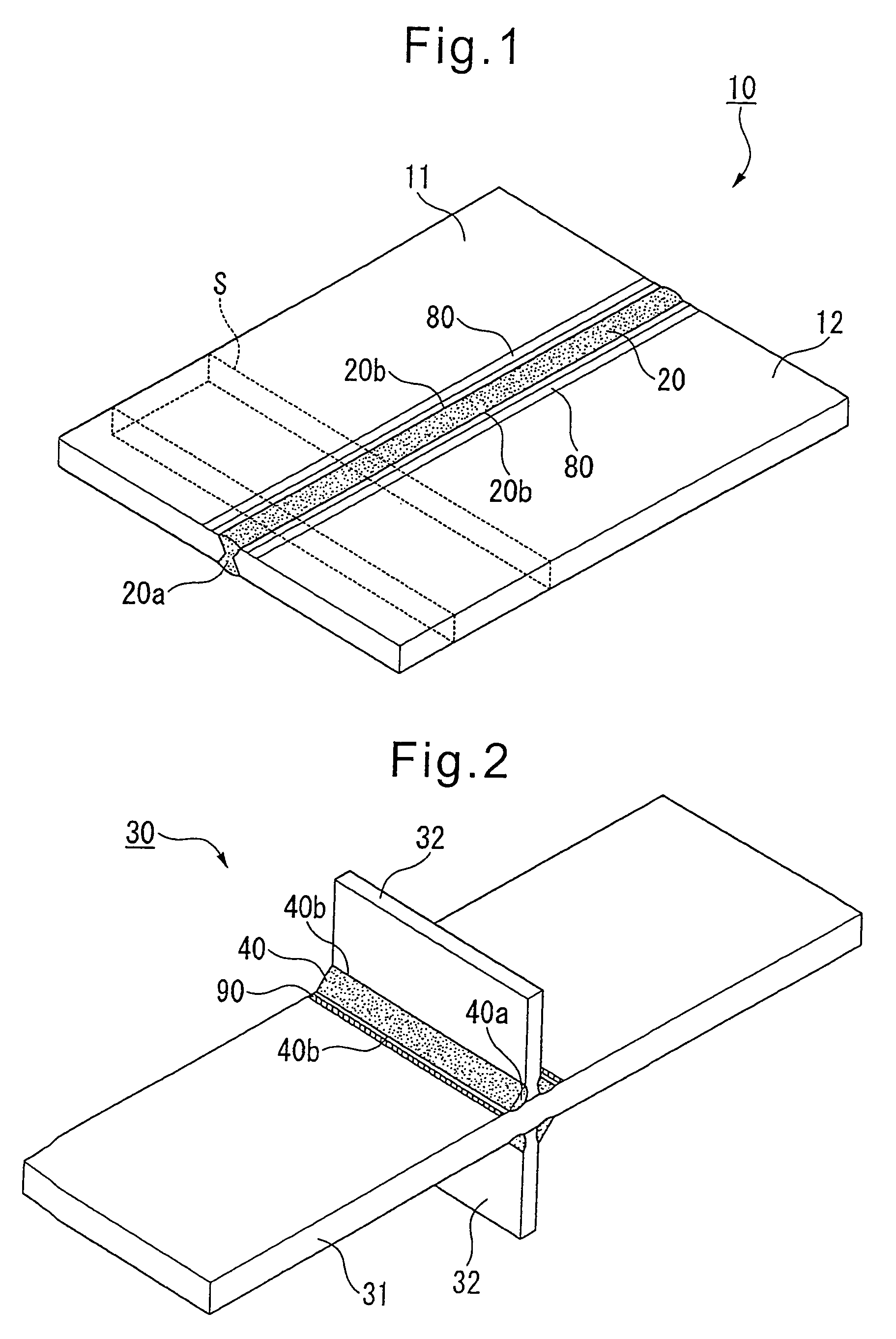
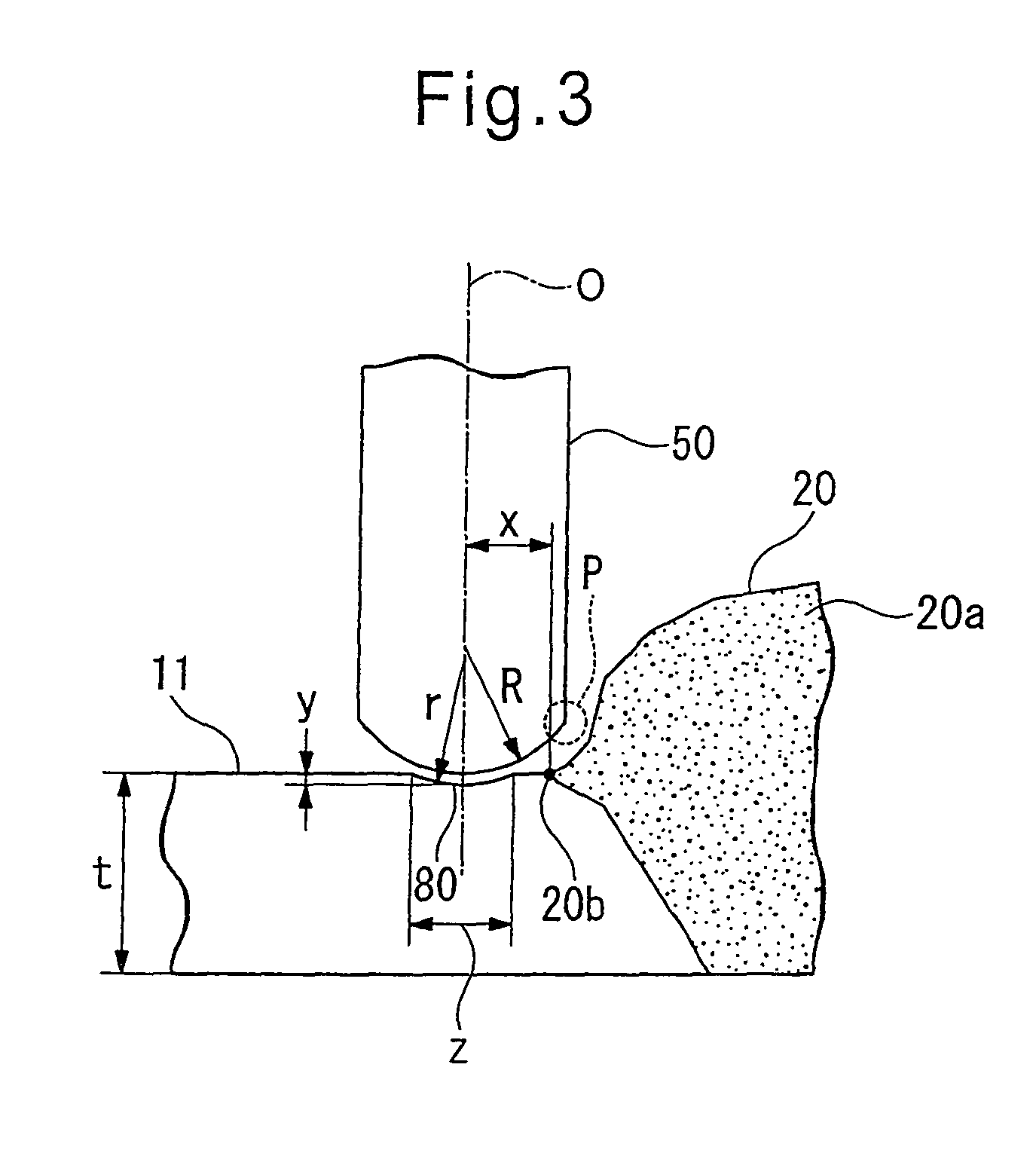
An impact treatment method for improving fatigue characteristics of a welded joint comprising pressing an impact pin against the surface of a base metal material near a toe of a weld bead and making it move relatively to the weld line direction to apply hammer peening treatment or ultrasonic impact treatment, characterized by using as the impact pin an impact pin having a tip curvature radius of ½ or less of a thickness of the metal material and between 2 to 10 mm and, on a surface of a base metal material up to a range where a distance from the toe of the weld bead to the center of the impact treatment position is within 2.5 times the tip curvature radius of the impact pin and where the impact pin does not contact the weld metal during impact treatment, applying hammer peening or ultrasonic impact treatment so as to cause by the impact pin residual plastic deformation where an impact dent has a groove depth of 0.1 to 2 mm, the tip curvature radius of the impact pin or less, and 1 / 10th or less of the thickness of the metal material and where the impact dent has a width of 1.5 to 15 mm and five times or more the groove depth.

Description

[0001]This application is a national stage application of International Application No. PCT / JP2009 / 063317, filed 21 Jul. 2009, which claims priority to Japanese Application No. 2008-193867, filed 28 Jul. 2008 which is incorporated by reference in its entirety.TECHNICAL FIELD[0002]The present invention relates to an impact treatment method for improving fatigue characteristics of a welded joint, an impact treatment device for improving fatigue characteristics of the same, and a welded structure superior in fatigue resistance characteristics. In particular, it relates to an impact treatment method for improving fatigue characteristics of a welded joint able to efficiently improve the fatigue characteristics of a welded joint, where occurrence of fatigue cracks becomes a problem, in metal members for structures subjected to repeated load used in buildings, ships, bridges, construction machines, industrial machines, offshore structures, automobiles, etc. and an impact treatment device f...

Claims


Application Information

Patent Timeline
Patent Type & Authority Patents(United States)
IPC IPC(8): C21D7/06B21D17/04
CPCC21D9/50C21D7/04C21D7/08B23K31/00B24C1/10Y10T428/12347
Inventor SHIMANUKI, HIROSHINOSE, TETSURO
Owner NIPPON STEEL CORP
Learn More