Circuit arrangement and method for operating a high pressure discharge lamp

a high pressure discharge and circuit arrangement technology, applied in the direction of lighting apparatus, electrical equipment, light sources, etc., can solve the problems of flickering, unfavorable power fluctuations, and the tendency of high pressure discharge lamps so as to reduce the tendency to flicker during operation, reduce the tendency to flicker, and reduce the effect of power fluctuations

Inactive Publication Date: 2014-06-24
OSRAM GMBH
View PDF14 Cites 0 Cited by
  • Summary
  • Abstract
  • Description
  • Claims
  • Application Information

AI Technical Summary

Benefits of technology

[0016]In such cases there is preferably a period of time between the consecutive setpoint values of the two phases which is between 1 ms and a few seconds, especially between 5 ms and 50 ms long. This enables a slow and low-cost control to be implemented which shows little tendency to flickering during operation.
[0020]Preferably the control arrangement determines a value representing the lamp wattage or the square wave lamp current in each phase individually and generates a setpoint value for each phase on the basis of the measured value. This allows the control arrangement to create a sufficiently precise setpoint value for each phase with little effort.
[0022]The control arrangement preferably generates the setpoint values at an interval which is between 1 ms in a few seconds long, especially between 5 ms and 50 ms long. This enables a slow and low-cost control to be implemented which exhibits less tendency to flicker during operation. The frequency of the setpoint values in such cases is preferably lower by at least one power than the frequency of the square wave lamp current.
[0023]In such cases the control arrangement preferably features a digital controller with a microcontroller. Since a microcontroller is implemented in many modern circuit arrangements for operating discharge lamps, the inventive control arrangement can be implemented as pure software, which cuts costs.

Problems solved by technology

With old lamps asymmetries in the lamp voltage sometimes occur, which can lead to undesired power fluctuations.
Rapid control steps with a small time constant however have the disadvantage of a tendency for the high pressure discharge lamp to flicker during its operation.
If the control has a very large time constant the tendency to flicker is small, but the asymmetries cannot be compensated for as a result of the large time constant of the control.

Method used


Image

  • Circuit arrangement and method for operating a high pressure discharge lamp
  • Circuit arrangement and method for operating a high pressure discharge lamp
  • Circuit arrangement and method for operating a high pressure discharge lamp

Examples


Embodiment Construction

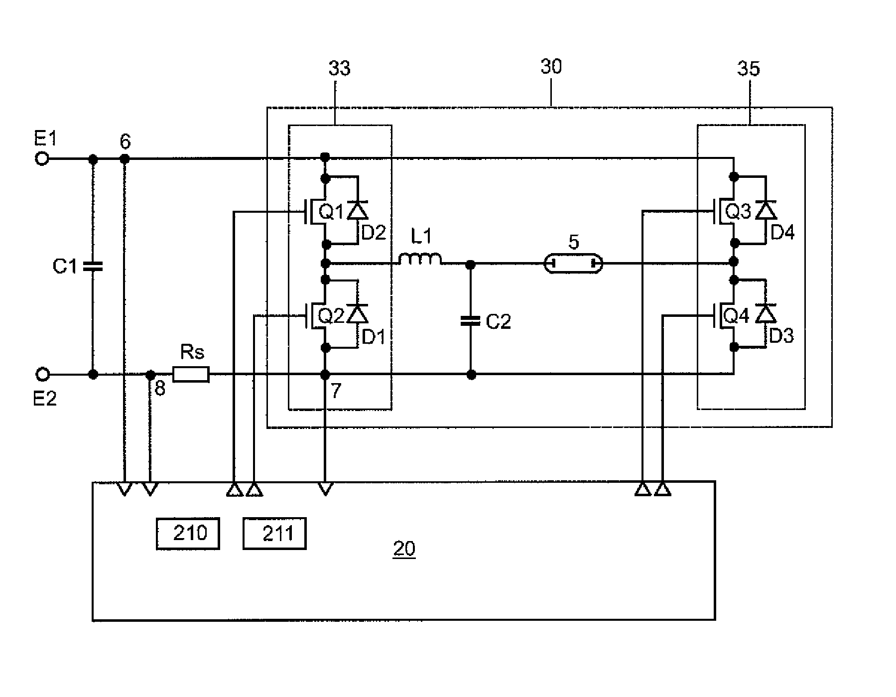
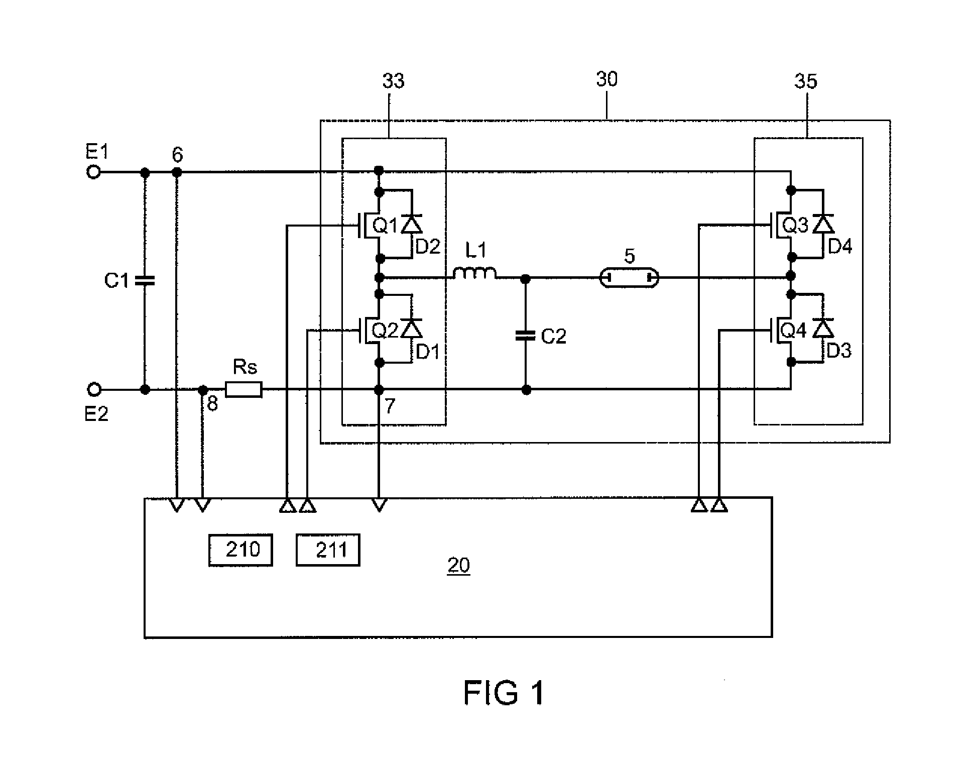
[0027]FIG. 1 shows a schematic block diagram of the circuit arrangement which carries out the inventive method. The circuit arrangement features a current inverter 30 with all parts which are needed for normal operation. Additional components such as ignition choke, ignition capacitor, driver circuits, etc. which are needed for starting a high-pressure discharge lamp 5 and for other conceivable operating states have been omitted for reasons of clarity. The current inverter 30 consists of a full bridge with 2 parallel-switched half bridges 33 and 35, which each have two switching transistors Q1, Q2 and also Q3, Q4. The switching transistors Q1-Q4 possess antiparallel free running diodes D1-D4. Connected between the center points of the two half bridges 33, 35 is a series circuit of the high pressure discharge lamp 5 and a lamp choke L1. Connected between the connection point of the high-pressure discharge lamp 5 and the lamp choke L1 and the connection point of the lower full-bridge ...


PUM


Abstract

A method for operating a high pressure discharge lamp, with the high pressure discharge lamp being operated by a current inverter with a square wave lamp current having a positive phase with positive current flow and a negative phase with negative current flow, and with the current inverter being controlled by a control arrangement wherein the method comprises the steps of measuring a value for the positive current flow representing the lamp wattage or the square wave lamp current, measuring a value for the negative current flow representing the lamp wattage or the square wave lamp current; calculating a predetermined setpoint value in each case from a guide variable of a lamp wattage or of the square wave lamp current and the measured value for the phase with positive current flow; calculating a predetermined setpoint value in each case from a guide variable of a lamp wattage or of the square wave lamp current and the measured value for the phase with negative current flow; and outputting the two predetermined setpoint values to the current inverter.

Description

RELATED APPLICATIONS[0001]This is a U.S. National Stage of application No. PCT / EP2008 / 064394, filed on Oct. 23, 2008.FIELD OF THE INVENTION[0002]The invention is related to a method and a circuit arrangement for operating a high pressure discharge lamp.BACKGROUND OF THE INVENTION[0003]High pressure discharge lamps are often operated with a square wave current of a lower frequency in order to simulate direct current operation. This operating mode is often referred to as intermittent DC mode. The frequency of the low-frequency square wave current in such cases is a maximum of one power greater than the input AC mains frequency. In principle a high pressure discharge lamp is thus operated in dc mode, but the polarity of the lamp current is regularly reversed in order to place an even load on the lamp electrodes.[0004]In such cases a power control system is generally implemented in order to operate the high pressure discharge lamp. With old lamps asymmetries in the lamp voltage sometime...

Claims


Application Information

Patent Timeline
Patent Type & Authority Patents(United States)
IPC IPC(8): H05B41/231H05B41/16
CPCH05B41/2925H05B41/288H05B41/292
Inventor BRAUN, ALOISLIMMER, WALTERSCHMIDL, MAXIMILIAN
Owner OSRAM GMBH
Why Eureka
Try Eureka