Spray booth system and methods

a booth and spray booth technology, applied in the field of spray booths, can solve the problems of affecting the maximum amount of air being filtered through the plenum, taking up to 40 minutes for the entire vehicle, etc., and achieve the effect of increasing the speed of the fan and increasing the airflow

Inactive Publication Date: 2014-06-24
THE PAINT BOOTH GUYS
View PDF40 Cites 18 Cited by
  • Summary
  • Abstract
  • Description
  • Claims
  • Application Information

AI Technical Summary

Benefits of technology

The spray booth has a unique design with walls, ceiling, and spacers. Fans are attached to the spacers, which allows air to flow at an angle between 20 degrees and 70 degrees. This allows air to flow into the fan and be emitted as airflow to spray or cure an object within the booth. Users can control each fan to gradually increase or decrease airflow, and to pulse, creating even heating over the surface of the object.

Problems solved by technology

Even at elevated temperatures and a down draft of semi-vertical draft, it can take up to 40 minutes for the entire vehicle to dry sufficiently to permit removal from the spray booth.
However, having filter media on the top side plenum directly above the fan hinders the maximum amount of air being filtered through the plenum, particularly if air is not directly added into the filter.

Method used


Image

  • Spray booth system and methods
  • Spray booth system and methods
  • Spray booth system and methods

Examples


Embodiment Construction

[0034]In the following detailed description of the preferred embodiments, reference is made to the accompanying drawings, which form a part thereof, and within which are shown by way of illustration specific embodiments by which the invention may be practiced. It is to be understood that other embodiments may be utilized and structural changes may be made without departing from the scope of the invention.

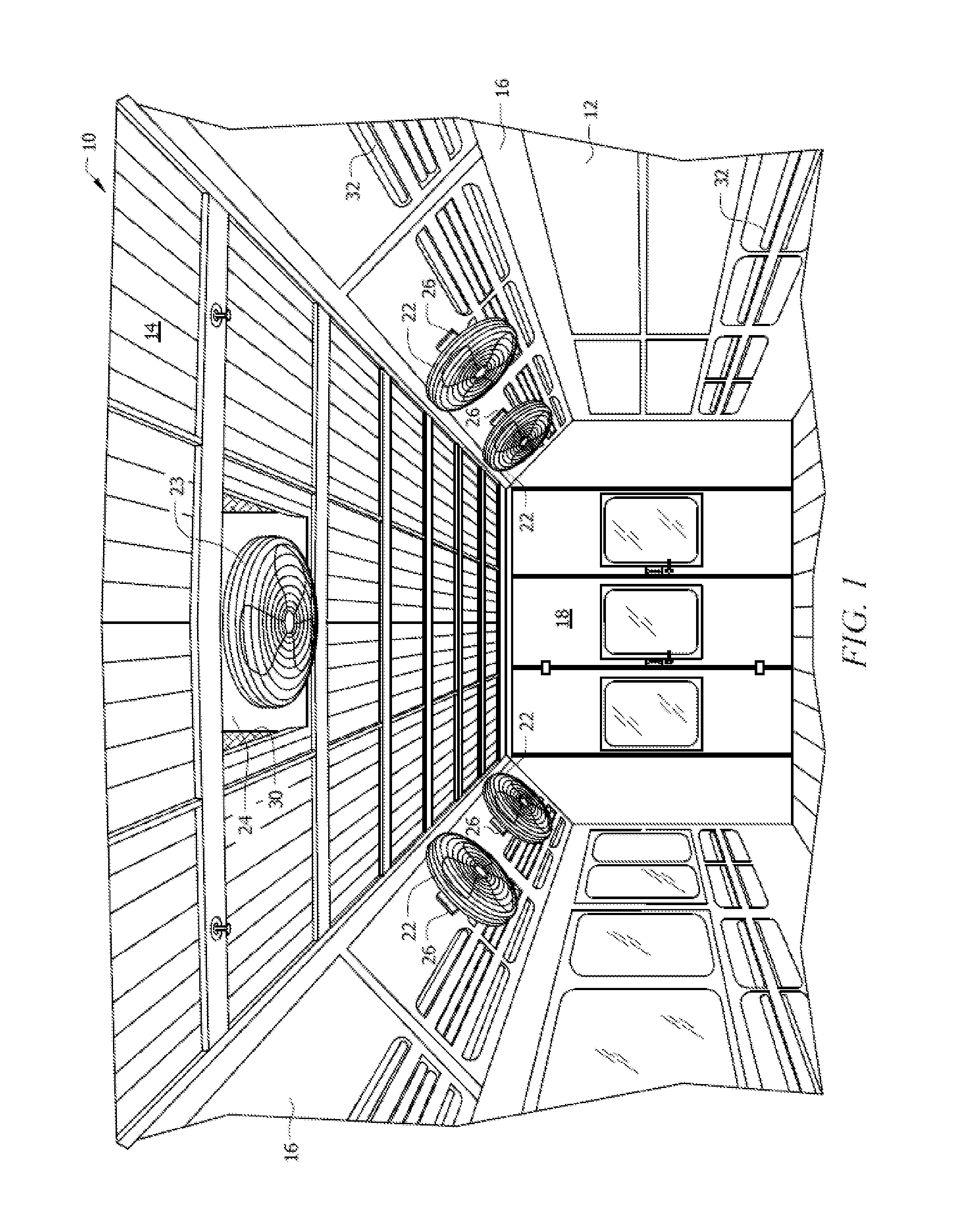
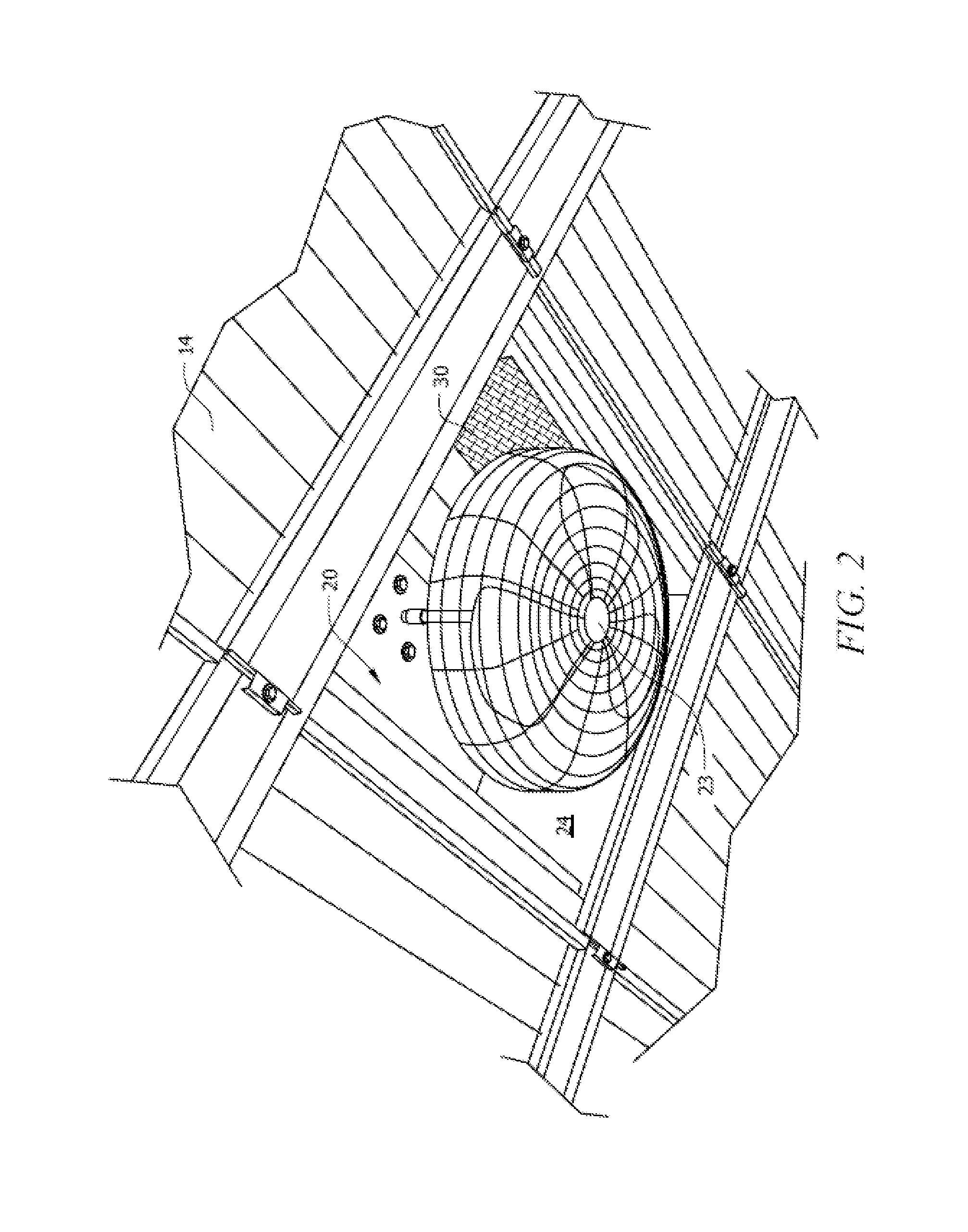
[0035]As depicted in FIG. 1, the claimed invention includes a spray booth generally denoted as reference 10. Spray booth 10 includes spray booth housing 12 having ceiling 14 and side walls 16 that define interior 18 for holding object 34 to be sprayed, such as a vehicle. Pressurized air plenum 20 is disposed above ceiling 14 and is adapted to supply air into interior 18 similar to U.S. Pat. No. 7,045,013, which is hereby incorporated by reference. Filter media 30 is used to filter air from plenum 20 before entering into interior 18. At least one fan 22 is disposed within spray booth...


PUM


Abstract

The current invention discloses a novel spray booth containing a plurality of spacers disposed on the walls or ceiling, and a plurality of fans attached to the spacers. A spacer allows a fan to be disposed at an angle and at a certain distance away from the wall or ceiling, allowing sufficient airflow for spraying or curing an object within the housing. Having fans emit airflow toward both the top and the sides of an object allows optimal coating and heating of the object. A ceiling fan may also be disposed within a plenum in the ceiling of the spray booth.

Description

CROSS-REFERENCE TO RELATED APPLICATIONS[0001]This application claims priority to U.S. Provisional Application No. 61 / 485,389, entitled “Spray Booth System and Methods,” filed on May 12, 2011, the contents of which are hereby incorporated by reference into this disclosure.BACKGROUND OF THE INVENTION[0002]1. Field of the Invention[0003]This invention relates generally to spray booths. More specifically, it relates to the creation of airflow onto the surface of an object without the addition of external air into the spray booth.[0004]2. Description of the Related Art[0005]When painting a vehicle or other object, drying or curing times can limit the amount of throughput. One common way to spray a vehicle is by using a spray booth. These booths provide advantages such as reducing particulate, confining paint overspray and evaporated solvents, and reducing drying times. To accelerate drying, air is flowed through the booth and over the vehicle. For waterborne paints, water in the paint tr...

Claims


Application Information

Patent Timeline
IPC IPC(8): F26B3/00
CPCF26B2210/12B05B16/60
Inventor CALABRO, MATTHEW A.CALABRO, JAMES P.
Owner THE PAINT BOOTH GUYS
Why Eureka
Try Eureka