
Catheters and related devices for forming passageways between blood vessels or other anatomical structures

a technology of blood vessels and catheter shafts, applied in the field of medical devices and methods, can solve the problems of perforation or trauma of tissue(s) other than those intended to be canalized, and the catheter shaft may lack sufficient structural integrity to efficiently transfer torque, etc., to achieve precise rotational control of the catheter, facilitate precise rotational positioning of the distal portion, and ensure the effect of stability

Inactive Publication Date: 2014-06-17
MEDTRONIC VASCULAR INC
View PDF118 Cites 69 Cited by
  • Summary
  • Abstract
  • Description
  • Claims
  • Application Information

AI Technical Summary

Benefits of technology

These solutions ensure precise rotational control and positioning of the catheter, reducing the risk of tissue trauma and improving the accuracy of forming interstitial passageways between blood vessels, while preventing unintended deployment of the tissue-penetrating element.

Problems solved by technology

If the catheter is improperly positioned or improperly oriented, the resultant passageway(s) may fail to perform their intended function (e.g., to channel blood from one location to another) or the tissue penetrating element of the catheter may perforate or traumatize tissue(s) other than those intended to be canalized.
However, when the passageway-forming catheter is formed of relatively small diameter, thin-walled polymeric material capable of navigating small, tortuous blood vessels, the catheter shaft may lack sufficient structural integrity to efficiently transfer torque from the proximal end of the catheter to the distal end thereof.

Method used


Image

  • Catheters and related devices for forming passageways between blood vessels or other anatomical structures
  • Catheters and related devices for forming passageways between blood vessels or other anatomical structures
  • Catheters and related devices for forming passageways between blood vessels or other anatomical structures

Examples


Embodiment Construction

[0064]The following detailed description and the accompanying drawings are provided for the purpose of describing and illustrating presently preferred embodiments of the invention only, and are not intended to limit the scope of the invention in any way.

[0065]It is to be appreciated that the individual elements and components of each of the embodiments described herebelow may be individually or collectively incorporated into each of the other embodiments capable of receiving or incorporating such element(s) or component(s), and no effort has been made to exhaustively describe all possible permutations and combinations of the inventive elements and components described herein.

i. Torqueable Introducer Sheath

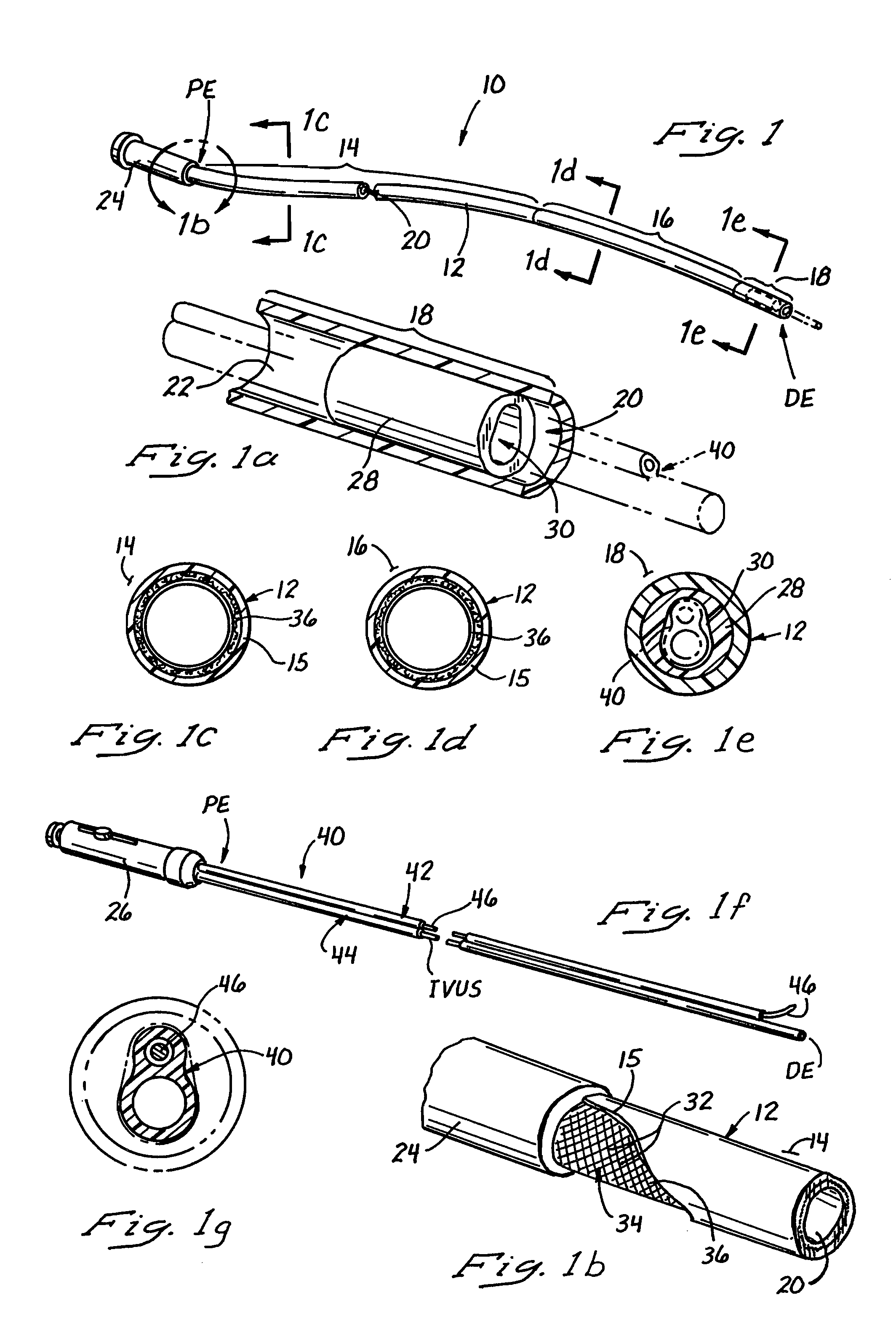
[0066]Referring specifically to FIGS. 1-1g, the present invention includes a torqueable introducer sheath 10 comprising an elongate pliable tubular sheath body 12 having a proximal end PE and a distal end DE. The tubular sheath body 12 comprises a proximal segment 14, a medial segm...


PUM


Abstract

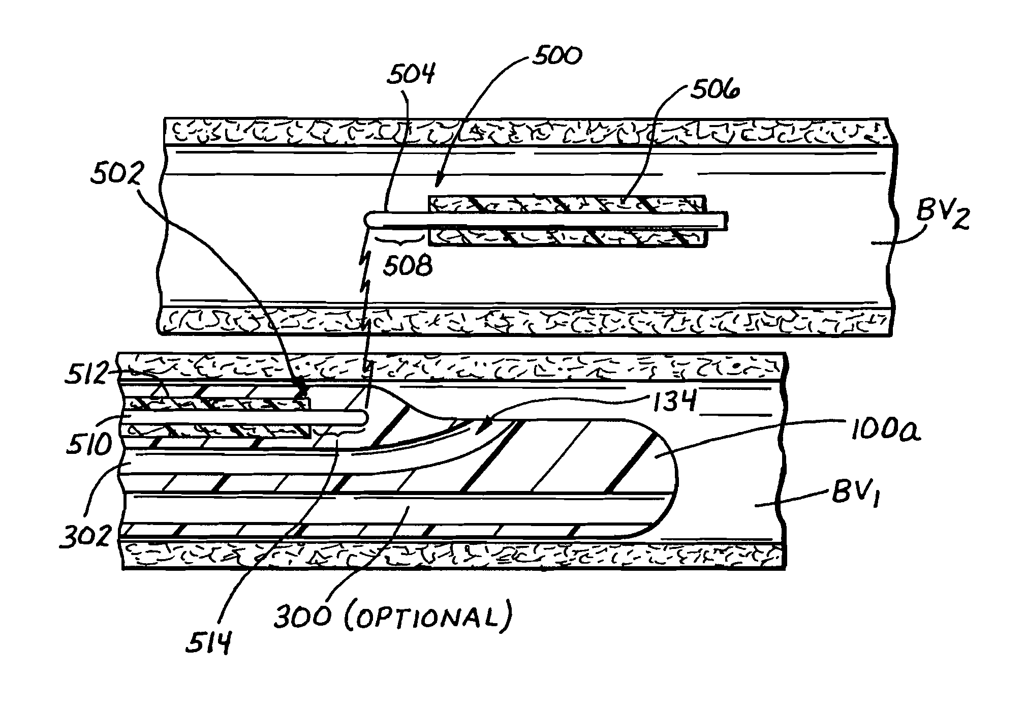
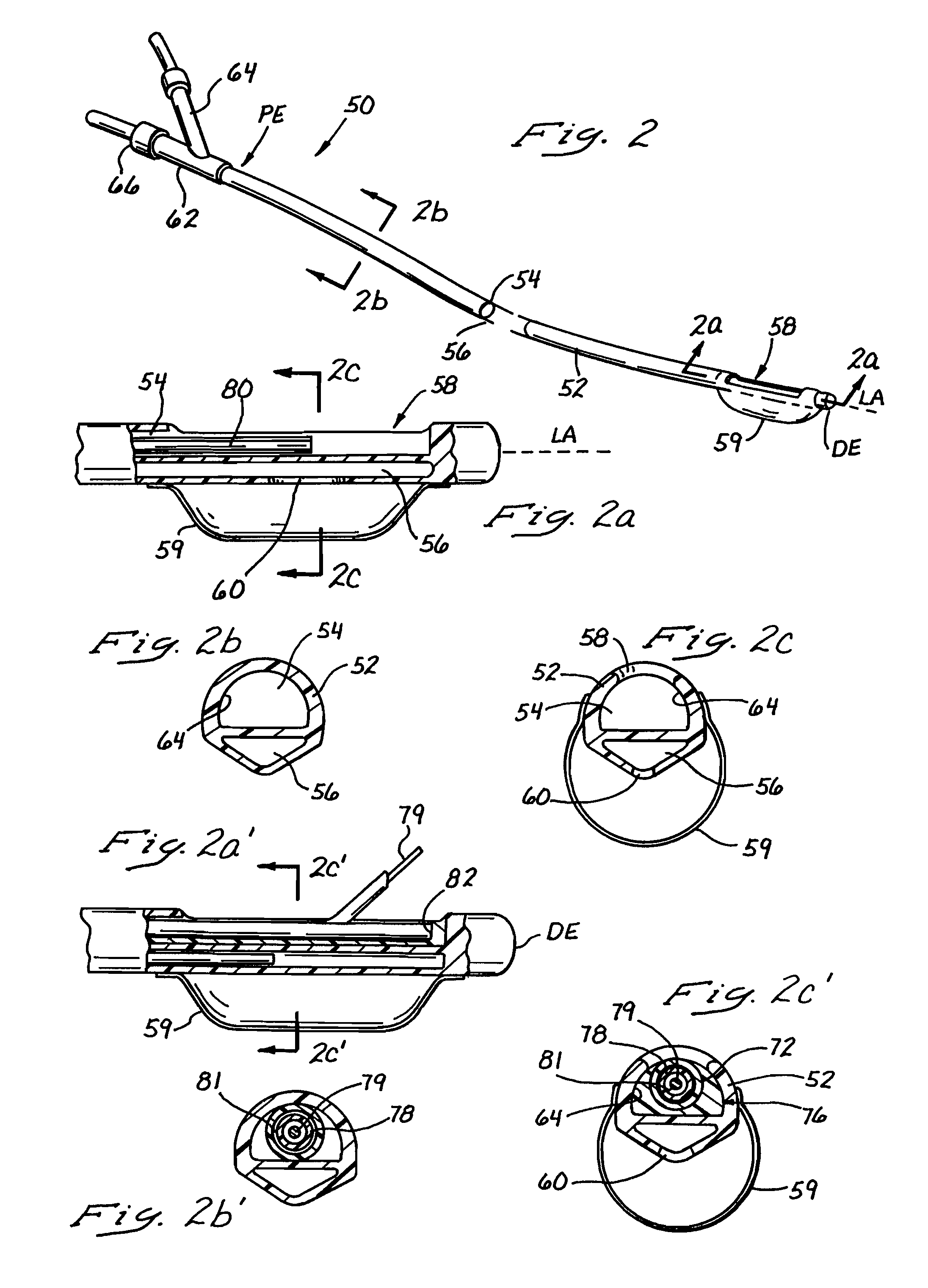
The inventions described in this patent application include i) a torqueable introducer sheath which is useable in conjunction with a transvascular passageway forming catheter to effect precise rotational control of the catheter; ii) an anchorable guide catheter which is useable in conjunction with an intravascular imaging catheter and a transvascular passageway-forming catheter to effect precise positioning and aiming of the passageway-forming catheter; iii) a passageway forming catheter having a torqueable proximal portion to facilitate precise rotational positioning of the distal portion of the catheter; iv) a deflectable-tipped passageway forming catheter, v) various markers and other apparatus useable in conjunction with any of the passageway-forming catheters to facilitate precise positioning and aiming of the catheter, and vi) an apparatus which may be formed within a catheter to prevent a member, apparatus of flow of material from being inadvertently advanced through a lumen of the catheter.

Description

RELATED APPLICATION[0001]This patent application is a divisional of U.S. patent application Ser. No. 09 / 912,122 filed Jul. 24, 2001, which is a divisional of U.S. patent application Ser. No. 08 / 837,294 filed Apr. 11, 1997, now U.S. Pat. No. 6,302,875, which is a continuation-in-part of the following: U.S. patent application Ser. No. 08 / 730,327 filed Oct. 11, 1996, now U.S. Pat. No. 6,190,353, which further claims priority to and incorporates by reference U.S. Provisional Application Nos. 60 / 005,164 filed Oct. 13, 1995 and 60 / 010,614 filed Feb. 2, 1996, and U.S. patent application Ser. No. 08 / 730,496 filed Oct. 11, 1996, now U.S. Pat. No. 5,830,222, which further claims priority to U.S. Provisional Application No. 60 / 005,164 filed Oct. 13, 1995.FIELD OF THE INVENTION[0002]The present invention relates generally to medical devices and methods, and more particularly to catheters, catheter positioning / aiming systems, and related methods for forming interstitial passageways (e.g., inters...

Claims


Application Information

Patent Timeline
Patent Type & Authority Patents(United States)
IPC IPC(8): A61B17/12A61B8/12A61F2/00A61M29/00A61B17/22A61B1/04A61B17/00A61B18/00A61F2/02A61B19/00A61B1/00A61M25/00A61B17/30A61B17/34A61M25/095A61M25/01A61B18/14A61B17/11A61B17/064A61B17/32
CPCA61M25/0155A61B2019/5429A61B17/12109A61B17/3417A61B17/11A61B2017/347A61M2025/1052A61M29/00A61B2019/5425A61B17/3439A61F2002/30079A61M25/0141A61B2017/306A61B17/00491A61B2017/22069A61B2018/00392A61B2017/22068A61B17/12045A61B18/00A61B17/3207A61B2017/00243A61M2025/009A61B2019/5276A61B18/1492A61B17/12136A61B19/38A61B2017/1107A61B8/4488A61B19/54A61M25/0147A61B2017/00252A61B2017/22067A61M29/02A61B2019/4857A61F2/2493A61B17/0643A61B17/12022A61B18/1477A61B2017/22072A61F2210/009A61B2017/003A61B2017/00247A61B2017/00504A61M2025/0076A61M25/0084A61B2017/12127A61B8/12A61B2017/1139A61B2018/1425A61B8/445A61B90/40A61B2090/0811A61B2090/378A61B90/39A61B2090/3925A61B2090/3929A61B17/3478
Inventor MAKOWER, JOSHUAFLAHERTY, J. CHRISTOPHERMACHOLD, TIMOTHY R.WHITT, JASON BRIANEVARD, PHILIP CHRISTOPHERMACAULAY, PATRICK EDWARDGARIBOTTO, JOHN THOMASTUMAS, MARGARET W.SELFRIDGE, ALAN ROBERT
Owner MEDTRONIC VASCULAR INC
Learn More