Method and apparatus of precisely measuring intensity profile of X-ray nanobeam

a technology of intensity distribution and intensity measurement, which is applied in the direction of instruments, imaging devices, nuclear engineering, etc., can solve the problems of difficult to determine the phase error of the surface of the x-ray mirror, difficult to prepare the geometrically sharp knife edge, and enhance the noise generated at intensity measurement, so as to achieve low background noise and enhance the signal level , the effect of increasing the s/n ratio

Inactive Publication Date: 2014-06-03
JTEC +1
View PDF2 Cites 2 Cited by
  • Summary
  • Abstract
  • Description
  • Claims
  • Application Information

AI Technical Summary

Benefits of technology

[0018]According to a method and apparatus for precise measurement of an X-ray nanobeam intensity distribution in the present invention, a diffraction X-ray intensity can be directly detected in proportion to an X-ray intensity at the leading end position of a knife edge in a geometrically dark section, which eliminates the need for differential processing required in the conventional wire scanning method and thus allows measurement with low background noise. In addition, the knife edge is made of a heavy metal with the effect of advancing a phase of an X-ray passing through the knife edge, a thickness of the knife edge is set so as to obtain a phase shift with which a transmission X-ray and a diffraction X-ray diffracted at the leading end of the knife edge reinforce each other, and an X-ray formed by overlapping of the diffraction X-ray and the transmission X-ray is measured by an X-ray detector. This enhances a signal level, which increases an S / N ratio allowing measurement of an X-ray intensity distribution with high sensitivity and high spatial resolution. In particular, it is possible to measure an intensity distribution of an X-ray nanobeam collected with a full width at half maximum of a beam waist of 100 nm or less, with nm-order spatial resolutions.
[0019]In addition, the thickness of the knife edge is changed continuously or stepwise with respect to the optical axis of an X-ray, and the edge member with the knife edge is run in a direction that changes in thickness and is orthogonal to the direction of the optical axis, thereby allowing the knife edge to be optimum in thickness with respect to the wavelength of an X-ray. If a focal depth of an X-ray is shallow, although sensitivity is sacrificed, a thinner portion of the knife edge can be used to obtain a sharp profile. Further, if the wavelength of an X-ray is unknown, it is possible to obtain a wavelength range of the unknown X-ray by deriving the thickness of the knife edge with a maximum diffraction X-ray intensity with respect to the X-ray of an unknown wavelength, or deriving thickness-intensity measurement characteristics from measurement of changes in diffraction X-ray intensity with respect to changes in thickness of the knife edge, and determining the wavelength range by back calculation from comparison between the thickness-intensity measurement characteristics and thickness-intensity calculation characteristics obtained by calculating the diffraction X-ray intensity with respect to the wavelength of the X-ray and the thickness of the knife edge.

Problems solved by technology

Accordingly, it is extremely difficult to determine a phase error in a surface of an X-ray mirror with respect to an ideal surface by off-line measurement using an interferometer or the like.
However, the wire scanning method has two problems: it is difficult to prepare a geometrically sharp knife edge with a sufficient thickness so as not to let an X-ray pass through; and noise generated at intensity measurement is enhanced at the time of differentiation.
In addition, although accurate information is needed in a wide base region of an X-ray intensity profile to calculate precisely a phase error of an X-ray mirror by phase retrieval, the conventional wire scanning method provides information in this region with low reliability.

Method used


Image

  • Method and apparatus of precisely measuring intensity profile of X-ray nanobeam
  • Method and apparatus of precisely measuring intensity profile of X-ray nanobeam
  • Method and apparatus of precisely measuring intensity profile of X-ray nanobeam

Examples


Embodiment Construction

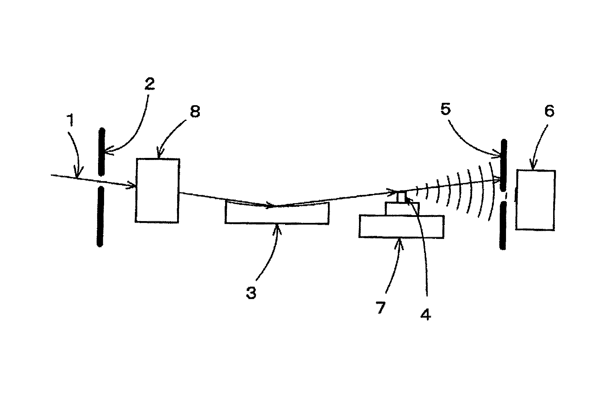
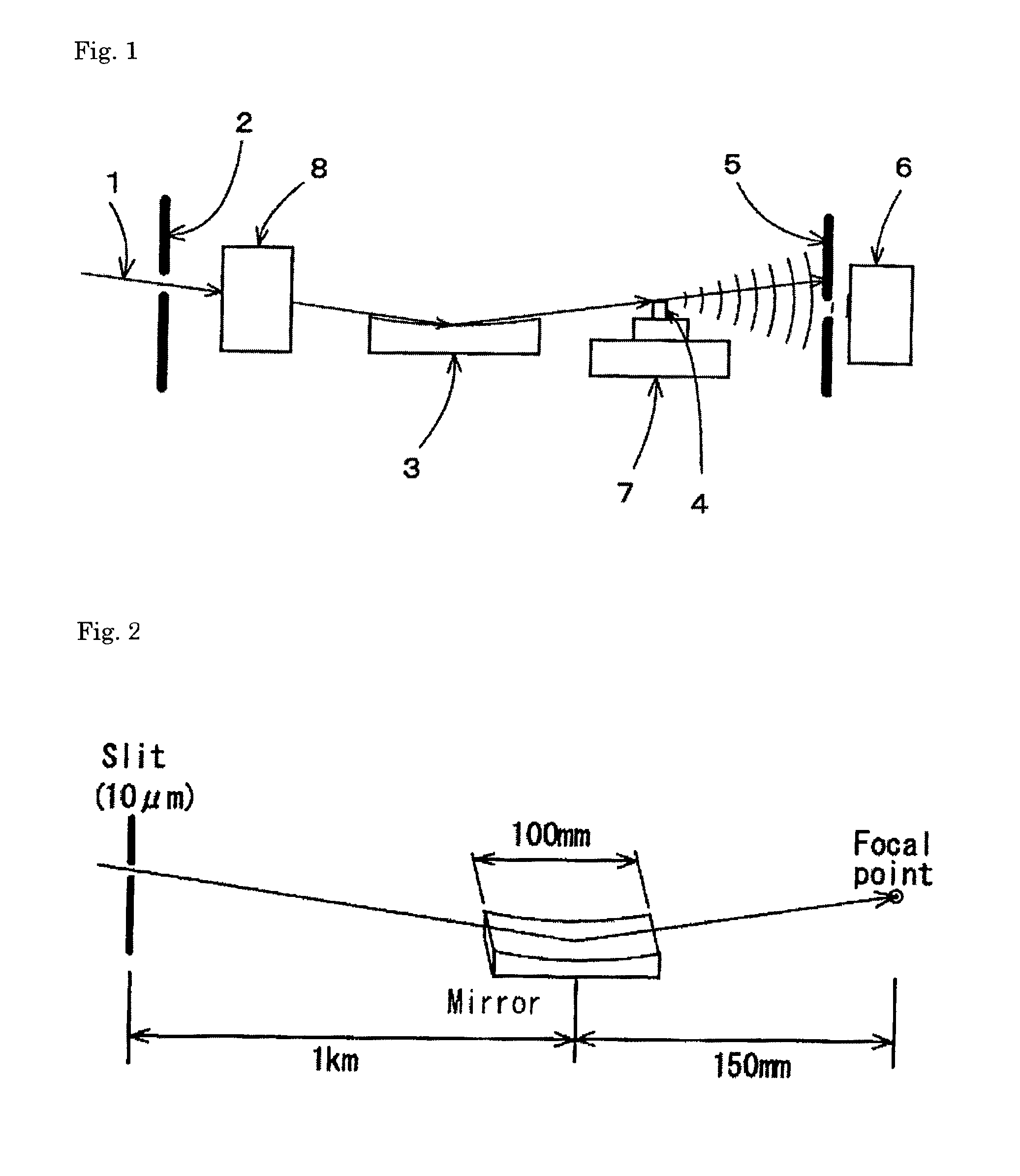
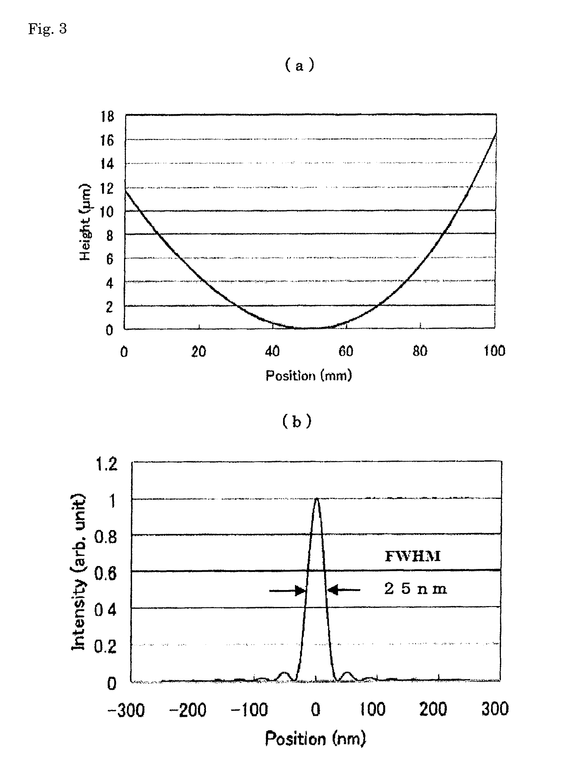
[0035]The present invention will be described in more detail with reference to the attached drawings. FIG. 1 is a general arrangement diagram of a measurement optical system using a method for precise measurement of an X-ray nanobeam intensity distribution, and FIG. 2 shows an X-ray beam collection optical system used for measurement.

[0036]In this embodiment, as shown in FIG. 1, an incident X-ray 1 passes through a slit 2 and obliquely enters into an X-ray mirror 3 having an oval form where the incident X-ray 1 is subjected to one-dimensional light collection. In addition, a knife edge 4 is disposed on an X-ray beam focal plane and a slit 5 is arranged behind the knife edge 4 to shut off a direct X-ray beam, and an X-ray intensity is measured by an X-ray detector 6 that is disposed behind the knife edge 4 at a position geometrically dark with respect to an X-ray source. The knife edge 4 is held by a moving stage 7, and the moving stage 7 is driven to run the knife edge 4 so as to cu...


PUM

PropertyMeasurementUnit
thicknessaaaaaaaaaa
inclination angleaaaaaaaaaa
thicknessaaaaaaaaaa

Abstract

Provided are a method and an apparatus of precisely measuring the intensity profile of an x-ray nanobeam, which can measure x-rays having different wavelengths with one knife edge and can perform optimal measurements corresponding to the depth of focus of an x-ray beam and the conditions of other measurement devices, using a dark field measurement method which enables precise measurements of the profile of an x-ray beam using a knife edge and using diffracted and transmitted x-rays. The knife edge (4) is formed of a heavy metal which advances the phase of an x-ray passing therethrough and is fabricated in such a manner that the thickness may change in the longitudinal direction continuously or in a stepwise fashion. The knife edge (4) is so set that an x-ray beam may traverse the knife edge (4) at such a thickness position as to achieve a phase shift in a range wherein a transmitted x-ray and a diffracted x-ray diffracted at the end of the knife edge may reinforce each other, and a superposed x-ray of the diffracted x-ray and the transmitted x-ray is measured by an x-ray detector.

Description

TECHNICAL FIELD[0001]The present invention relates to a method and apparatus for precision measurement of an X-ray nanobeam intensity distribution, and more specifically, to a method and apparatus for precision measurement of an X-ray nanobeam intensity distribution that make it possible to measure an intensity distribution of X-ray nanobeams in soft X-ray to hard X-ray regions, with nm-order spatial resolutions.BACKGROUND ART[0002]High-brightness, low-emittance, and high-coherence X-rays in various wavelength regions from soft X-rays to hard X-rays have become available at third-generation synchrotron radiation facilities represented by SPring-8. This has dramatically improved analytical sensitivities and spatial resolutions at various analyses such as fluorescent X-ray analysis, photoelectron spectrometry, and X-ray diffraction. These X-ray analyses and X-ray microscopic approaches using radiation light not only provide high sensitivities and high resolutions but also allow nondes...

Claims


Application Information

Patent Timeline
Patent Type & Authority Patents(United States)
IPC IPC(8): G01N23/20
CPCG21K2207/00G01N23/201G21K2201/06G01N23/207
Inventor YAMAUCHI, KAZUTOMIMURA, HIDEKAZUOKADA, HIROMI
Owner JTEC
Why Eureka
Try Eureka