
Multi-domain unified debugger

a debugger and multi-domain technology, applied in the field of debugging executed block diagram models, can solve the problems of not being able to provide the level of detail, the model is not usually accurate, and the generality of the description of dynamic system behavior is not suitabl

Active Publication Date: 2014-05-27
THE MATHWORKS INC
View PDF32 Cites 6 Cited by
  • Summary
  • Abstract
  • Description
  • Claims
  • Application Information

AI Technical Summary

Benefits of technology

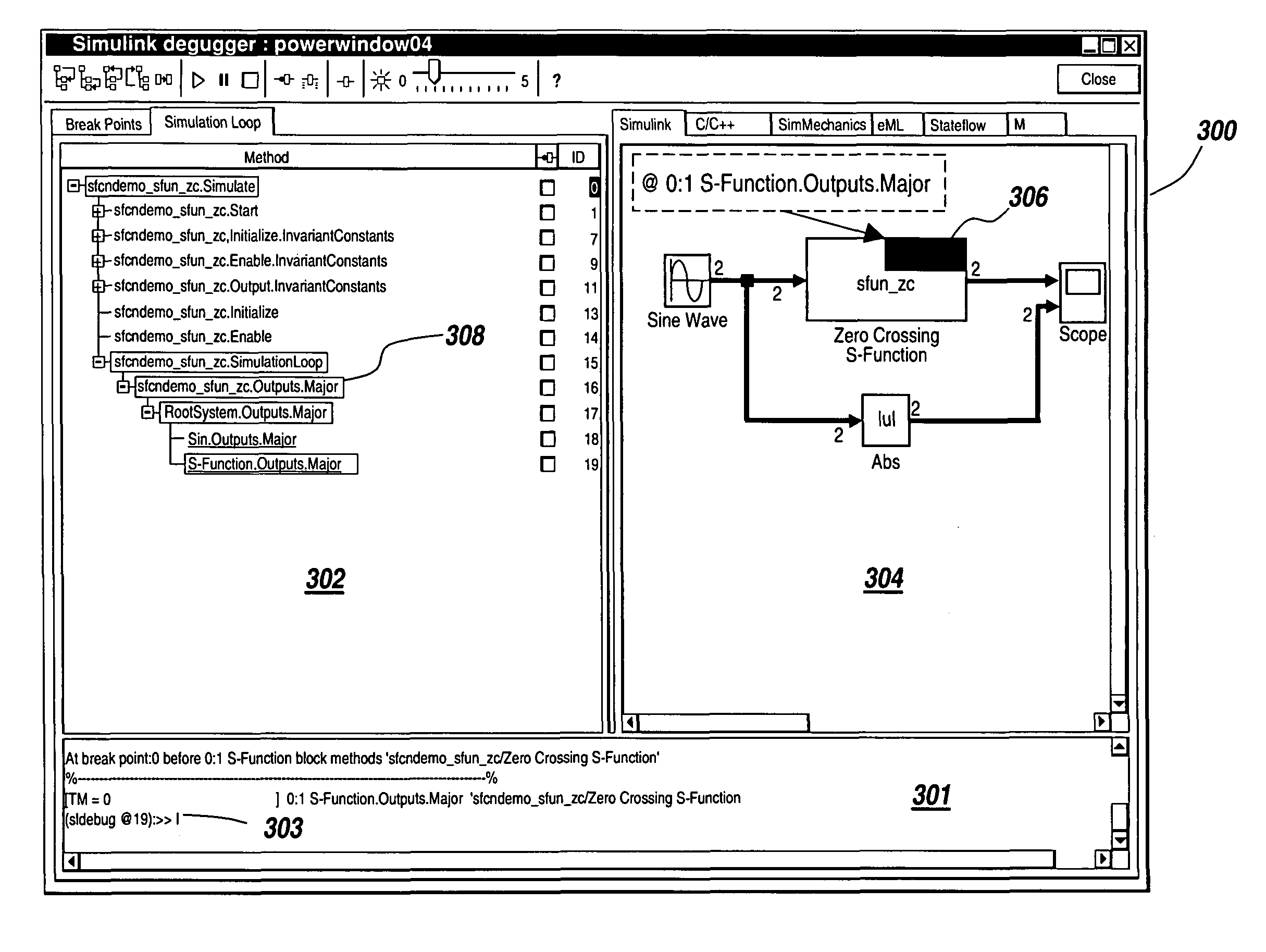
The present invention provides a multi-domain Unified Debugger that can support debugging of graphical models from different domains such as time-based block diagrams, statecharts, and physical system models. It also has additional features for debugging hand-written and automatically generated code. The Unified Debugger automatically generates a consistent view of the entity being executed based on its type of modeling domain. This saves time and effort for users who don't have to manually switch between different debuggers. The Unified Debugger also integrates diagnostic information from multiple modeling domains and allows for customization of pass-fail criteria for debugging.

Problems solved by technology

Such systems range from simple to highly complex systems.
Flow-charts are used to capture process flow and are not generally suitable for describing dynamic system behavior.
As systems become more complex, an increasingly large amount of time and effort is involved in creating accurate, detailed models.
Unfortunately, this level of detail is not usually available as the display and the accessibility of such detailed information introduces significant execution overhead.
Instead, the model can be run in a distinct ‘debug’ mode, where the additional information is exposed, but at the cost of execution speed.
Unfortunately, the individual debuggers do not work together as a seamlessly integrated tool over multiple domains.
This presents a number of problems.
Additionally, conventional debuggers provide no information about how the different domains of the system work together.

Method used


Image

  • Multi-domain unified debugger
  • Multi-domain unified debugger
  • Multi-domain unified debugger

Examples


Embodiment Construction

[0028]The illustrative embodiment of the present invention provides a Unified Debugger that integrates debugging and diagnostic information from multiple modeling domains that are referenced by entities in a block diagram. The multiple modeling domains include time-based block diagrams, statecharts, data flow diagrams and compiled code. The Unified Debugging environment is able to display domain appropriate views to a user automatically based upon the entity in the block diagram being debugged. Additionally, a standard diagnostic interface embodied in a block diagram debuggable object is defined allowing access to information from the multiple types of modeling domains. The use of the standard diagnostic interface enables the customization of debug behavior at the block diagram functional level.

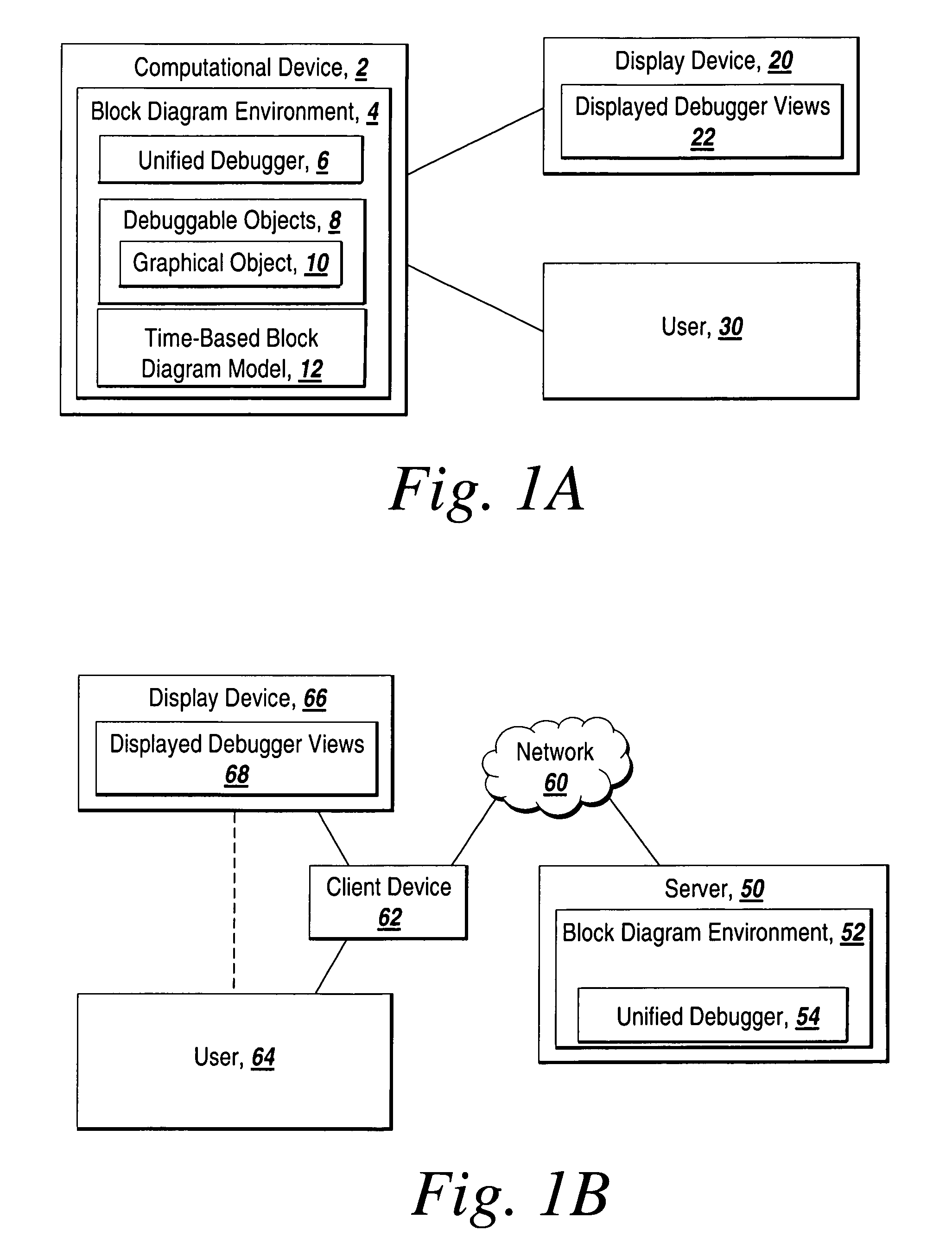
[0029]FIG. 1A depicts an environment suitable for practicing the illustrative embodiment of the present invention. A computational device 2 includes a graphical modeling environment such as t...


PUM


Abstract

A Unified Debugger that enables the debugging of graphical models with combinations of entities from multiple domains such as time-based block diagrams, statecharts, and physical system models, with additional features for the debugging of hand-written and automatically generated code is disclosed. A view of the entity being executed that is consistent with the type of the modeling domain to which the entity currently being executed belongs is automatically generated for a user. Rather than requiring a user to manually transition from one debugger to the next, the Unified Debugger applies the appropriate debugging features from each modeling domain. The Unified Debugger also enables integration of diagnostic information from a multitude of modeling domains into a central user interface. In addition, a standard diagnostic interface which spans a plurality of modeling domains is defined that enables the customization of debug behavior.

Description

RELATED APPLICATION[0001]This application is a continuation of U.S. patent application Ser. No. 11 / 025,218, filed Dec. 29, 2004, the entire content of which is incorporated by reference.FIELD OF THE INVENTION[0002]The illustrative embodiment of the present invention relates generally to the debugging of executed block diagram models, and more particularly to the debugging of block diagram models containing entities from multiple types of modeling domains using a Unified Debugger.BACKGROUND[0003]Block diagrams are used to model real-world systems. Historically, engineers and scientists have utilized time-based block diagram models in numerous scientific areas such as Feedback Control Theory and Signal Processing to study, design, debug, and refine dynamic systems. Dynamic systems, which are characterized by the fact that their behaviors change over time, are representative of many real-world systems. A dynamic system (either natural or man-made) is a system whose response at any give...

Claims


Application Information

Patent Timeline
Patent Type & Authority Patents(United States)
IPC IPC(8): G06F9/44
CPCG06F11/3664
Inventor MOSTERMAN, PIETER J.YUNT, MEHMETYEDDANAPUDI, MURALITORGERSON, JAY RYAN
Owner THE MATHWORKS INC
Learn More