
Vehicle electrical power management and distribution

a technology for electrical power management and vehicles, applied in the field of vehicle power systems, can solve the problems of increased engine fuel consumption, increased manufacturing or operational costs, and reduced fuel consumption or emissions resulting from engine operation, so as to reduce the power demand of vehicle engines and reduce the effect of fuel consumption or emissions

Active Publication Date: 2014-05-27
THE BOEING CO
View PDF202 Cites 25 Cited by
  • Summary
  • Abstract
  • Description
  • Claims
  • Application Information

AI Technical Summary

Benefits of technology

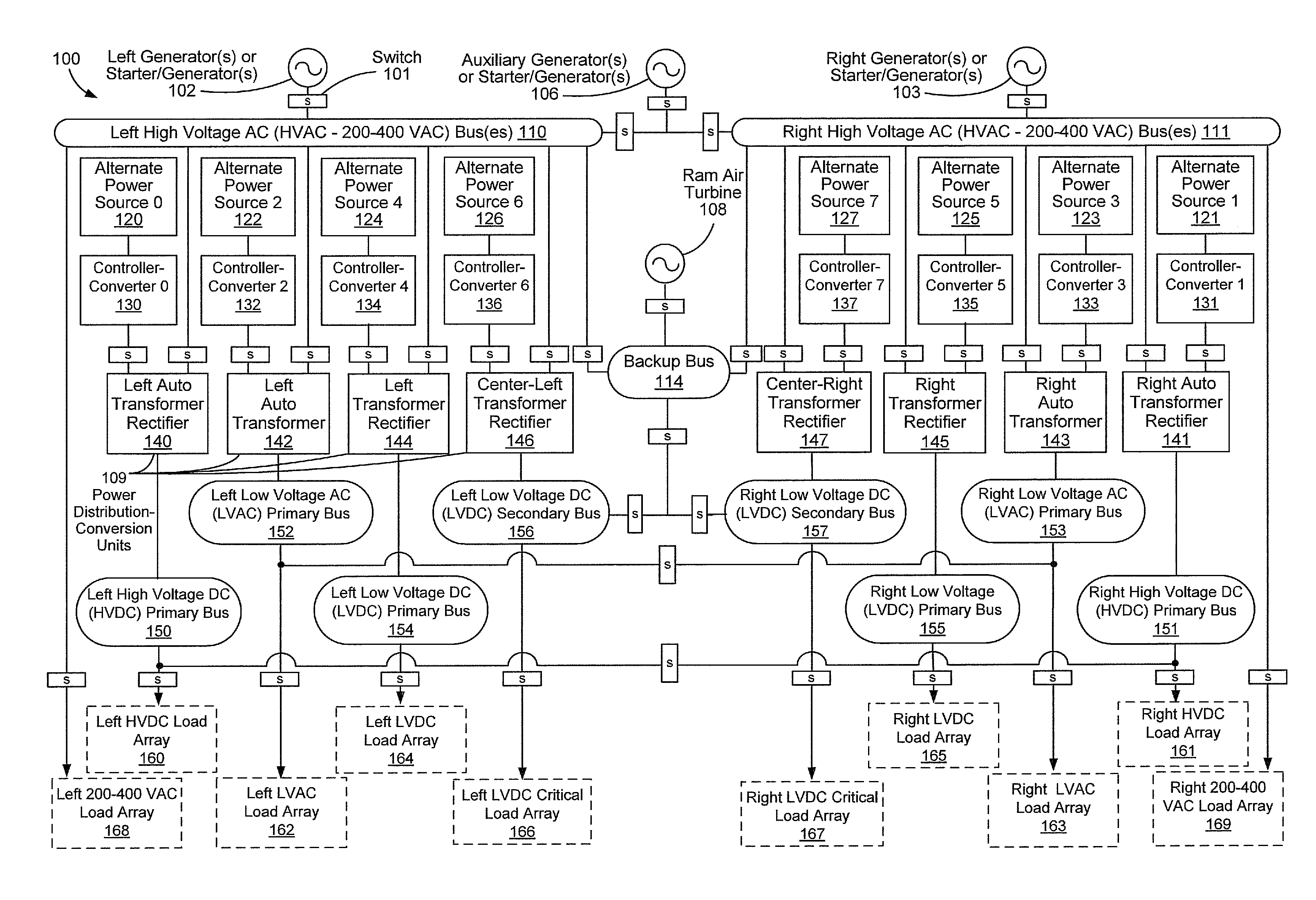
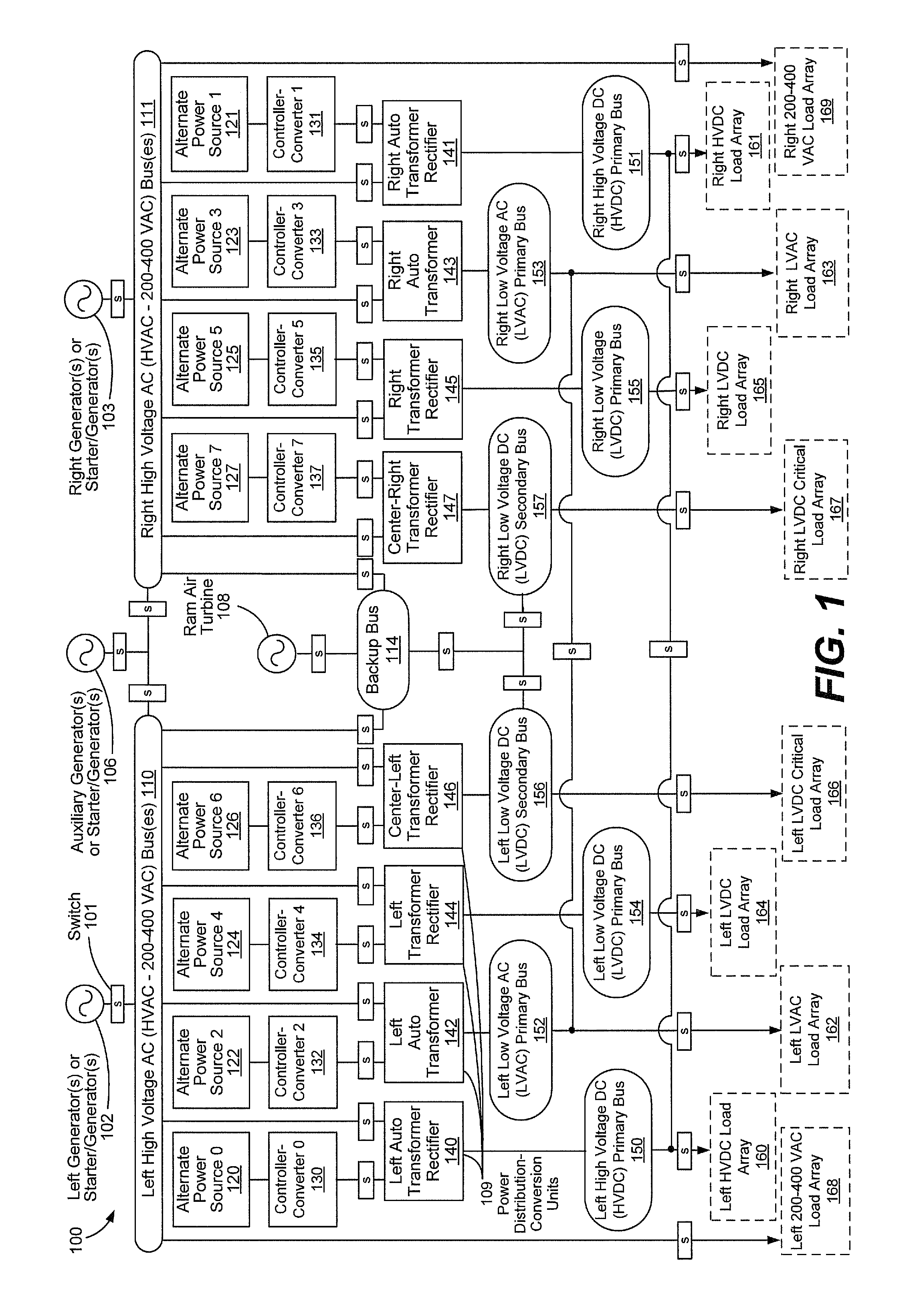
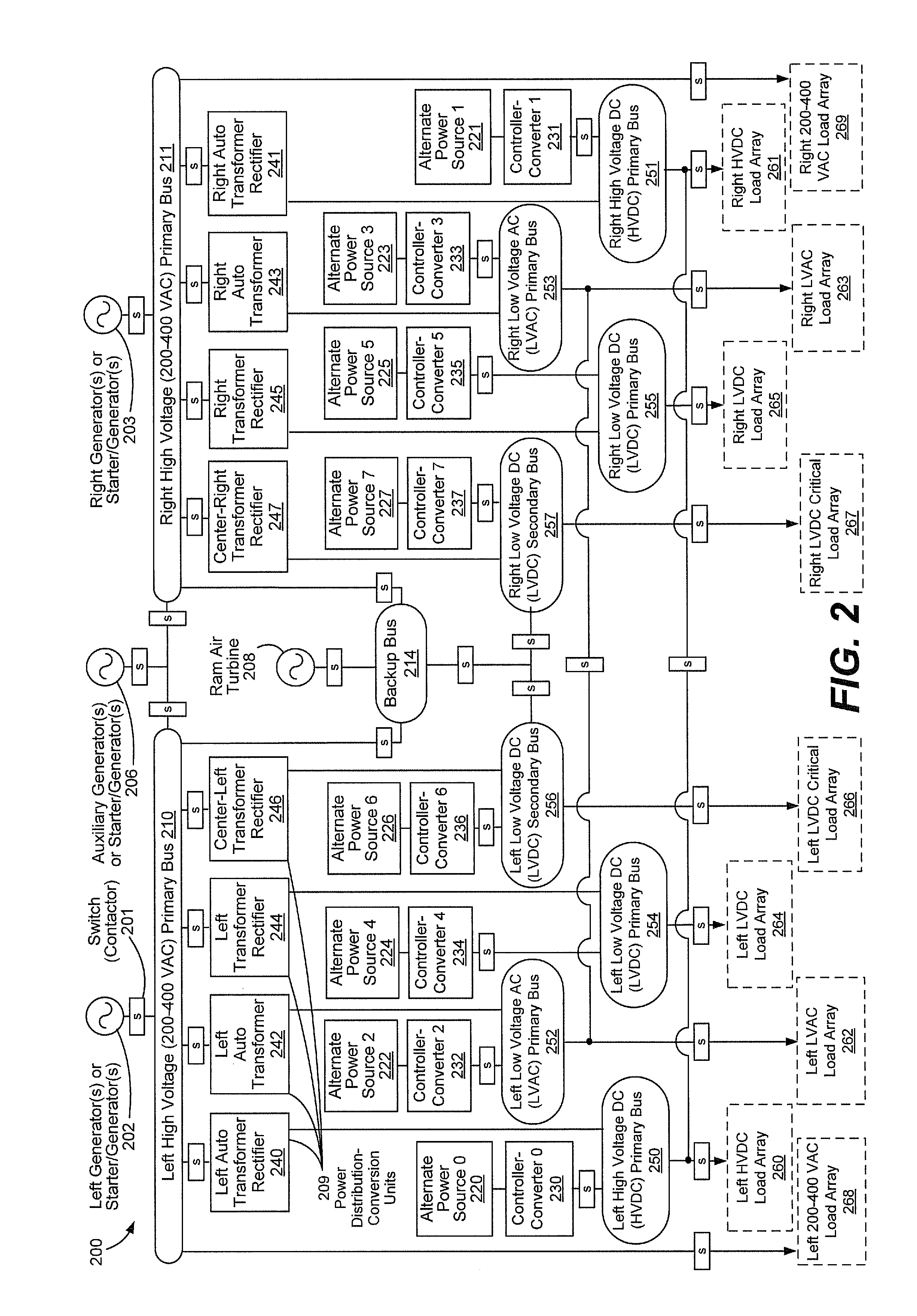
The patent text describes the use of alternative power sources, which can be used instead of the main engine in a vehicle to reduce power demands on the engine and decrease fuel consumption and emissions. The alternative power sources can be connected to the distribution bus or directly to loads or subsystems in different ways. The use of these sources can help to maintain power supply even when the engine is not running.

Problems solved by technology

Diverting power from the engine increases engine fuel consumption, and the engines may not operate at their highest efficiency.
Further, in other vehicle contexts or in non-vehicle contexts, the generators may be driven by turbines or other motivators powered by water, geothermal steam, wind, or other forces and, thus, may not be engine-driven.
Thus, when anticipated demand for a particular type of power may be met by a single alternate power source and a multi-function controller-converter, additional manufacturing or operational costs may be saved.
It is possible that, if power is not required by a bus or a load, that the bus or the load has failed.

Method used


Image

  • Vehicle electrical power management and distribution
  • Vehicle electrical power management and distribution
  • Vehicle electrical power management and distribution

Examples


Embodiment Construction

[0019]Embodiments disclosed herein include systems and methods of providing power to vehicle subsystems and of controlling distribution of power to vehicle subsystems. In a particular embodiment, instead of relying on a first power (or generator power) provided by engine-driven generators or other generators, one or more vehicle subsystems receive alternate power from one or more engine-independent power sources. By using engine-independent power sources, or “alternate power sources” (e.g., a fuel cell system, a battery, a recuperative actuator, a supercapacitor, etc., that provide power independently of one or more engines), some power demand may be removed from the engine-drive generators. Removing some of the power demand from the engine-driven generators may make the vehicle more fuel efficient or may reduce vehicle operating emissions. Additionally, the alternate power sources may provide faster dynamic response to power demands, as well as improved power availability and relia...


PUM


Abstract

Vehicles, systems, and methods are disclosed for providing and directing first power, such as vehicle generator power, and alternate sources of power. In a particular embodiment, a vehicle includes a power distribution grid that includes a plurality of power sources and a plurality of distributions buses configured to distribute power from the plurality of power sources. The plurality of power sources include an engine-driven power source is configured to provide first power where the first power has first power characteristics. The plurality of power sources also includes a plurality of engine-independent power sources including a first alternate power source configured to provide first alternate power. The first alternate power has first alternate power characteristics that are different than the first power characteristics. The plurality of engine-independent power sources also includes a second alternate power source configured to provide second alternate power. The second alternate power has second alternate power characteristics that are different from the first power characteristics and different from the first alternate power characteristics. The vehicle also includes a global controller that sends control signals to control generation of power by the engine-driven power source, the first alternate power source and the second alternate power source via the plurality of distribution buses responsive to power demand of the power distribution grid.

Description

FIELD OF THE DISCLOSURE[0001]The present disclosure is generally related to vehicle power systems.BACKGROUND[0002]A large or complex vehicle, such as a commercial aircraft, may include an electric power system that distributes power to various electrical subsystems at different voltage levels and different frequencies. For example, electrically-powered mechanical systems may use alternating current (AC) at relatively high voltage. By contrast, avionics systems conventionally operate on direct current (DC) at relatively low voltage. Other systems may also be present that use power of different characteristics.[0003]On an aircraft, electrical power is typically generated by engine-driven generators. For example, power from an engine aboard the aircraft may be diverted to drive a generator. The electrical power may be converted using transformers, power electronics converters, or combination of both, and other devices to either alternating or direct current at different voltages used b...

Claims


Application Information

Patent Timeline
Patent Type & Authority Patents(United States)
IPC IPC(8): G06F19/00G06G7/70
CPCY04S10/126B64D2221/00H02J3/38Y02E60/721Y10T307/50Y10T307/718Y10T307/305Y10T307/25Y10T307/406H02J2310/44Y02E60/00
Inventor KARIMI, KAMIAR J.LIU, SHENGYILIFFRING, MARK E.HELTON, STEVEN B.FU, SHEAU-WEI JOHNNY
Owner THE BOEING CO
Learn More