
Screw and nut assembly with screw rod support means

a technology of screw rod and support means, which is applied in the direction of gearing, manufacturing tools, hoisting equipment, etc., can solve the problems of high noise, excessive deformation of the screw rod, and high cost of pneumatic/hydraulic pressure-driven design, etc., and achieve the effect of less cos

Active Publication Date: 2014-05-27
HIWIN TECH
View PDF3 Cites 2 Cited by
  • Summary
  • Abstract
  • Description
  • Claims
  • Application Information

AI Technical Summary

Benefits of technology

[0005]The present invention has been accomplished under the circumstances in view. It is the main object of the present invention to provide a screw and nut assembly with screw rod support means, which enables the gap between the movable platform and each support to be changed subject to movement of the screw nuts, minimizing the stroke in which the platform is stopped from movement and, which is less expensive than conventional pneumatic or hydraulic pressure-driven designs.
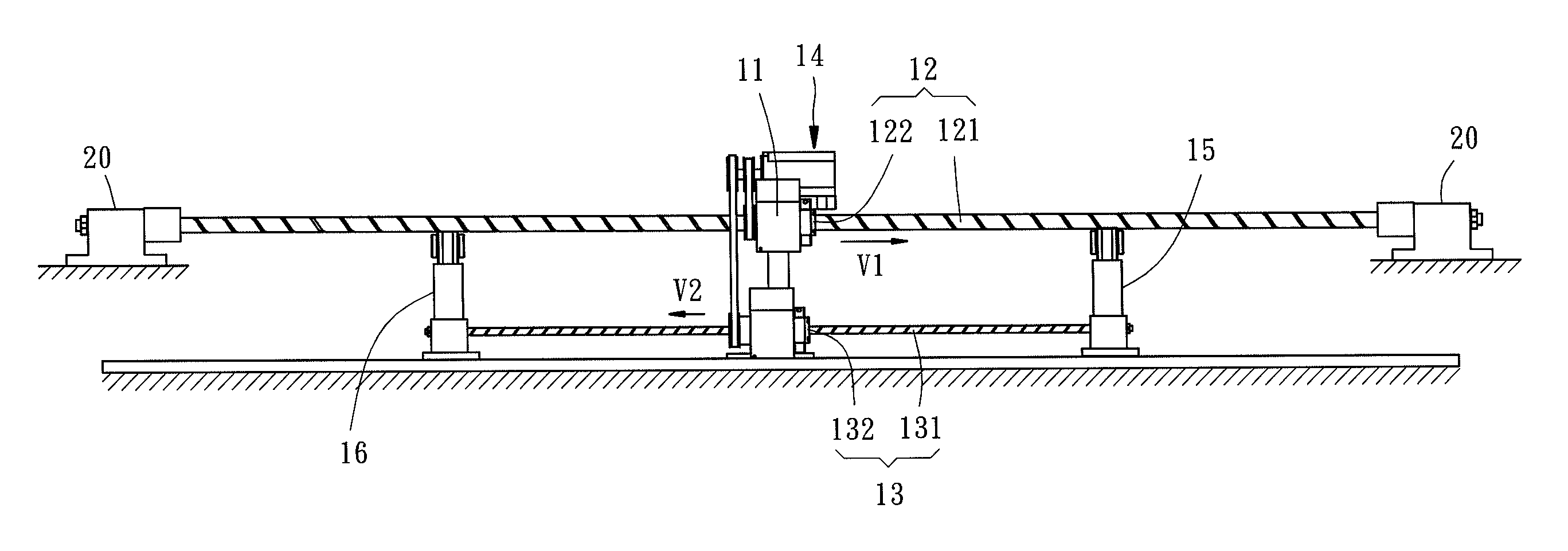
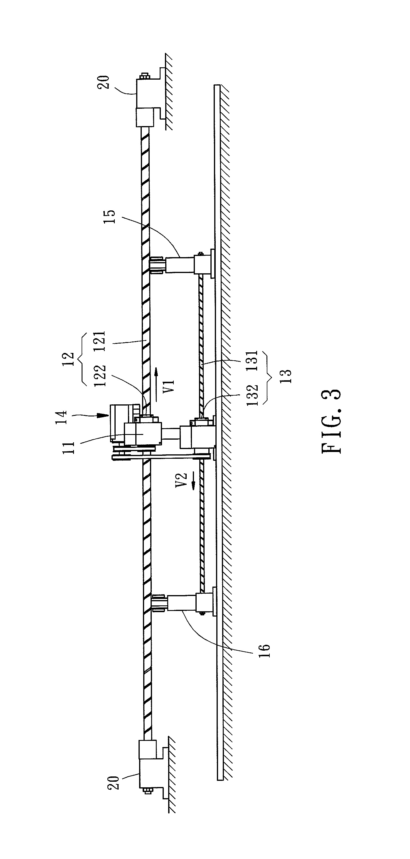
[0007]Thus, during movement of said movable platform on said first screw rod, said second screw nut and said first screw nut are moved in the same direction, minimizing the stroke in which the first screw nut is stopped from movement. This structural design is less expensive when compared to conventional pneumatic or hydraulic pressure-driven designs.

Problems solved by technology

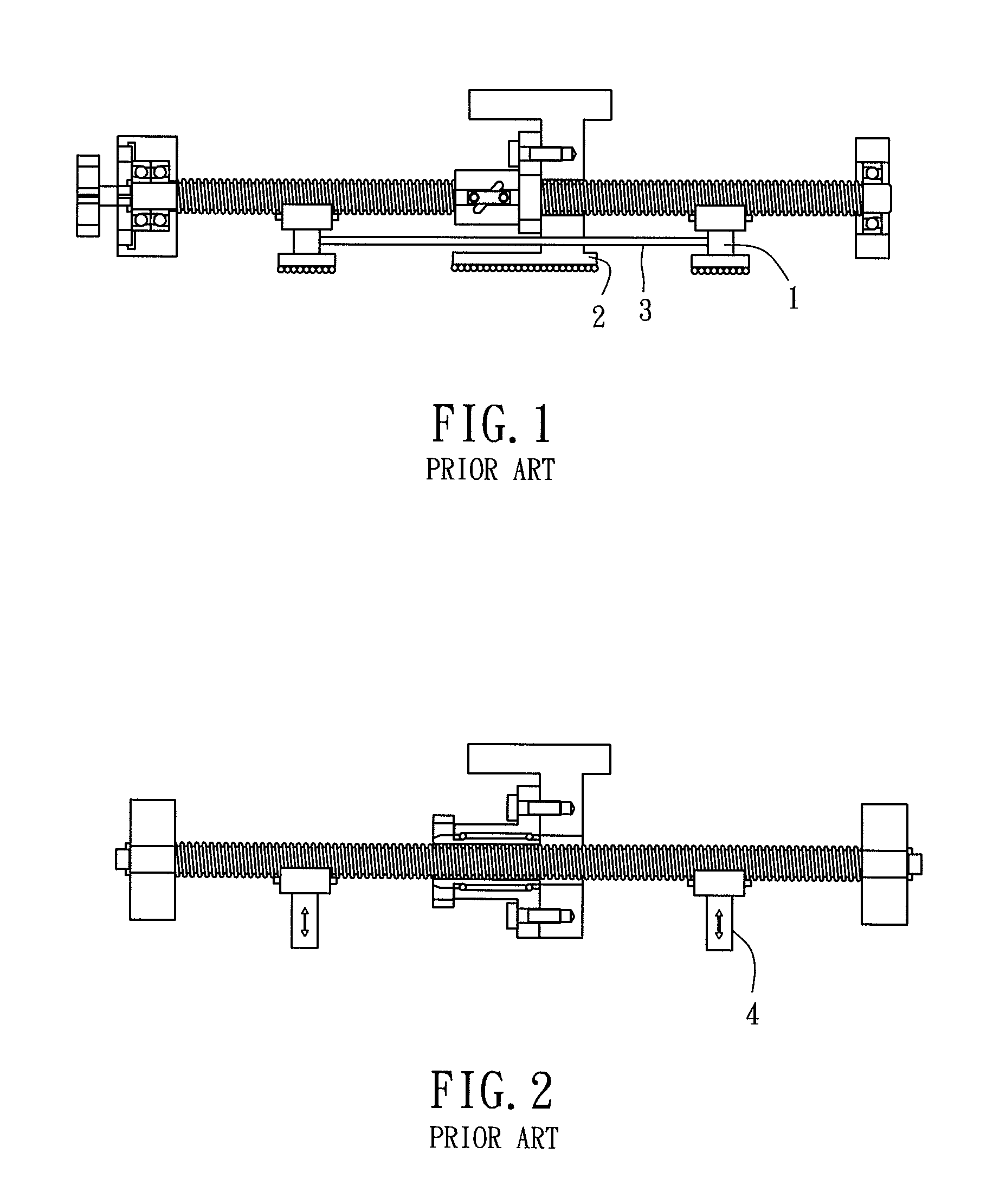
During operation, the screw rod may be excessively deformed.
As a result, the critical rotating speed of the screw rod will be constrained, and a high noise may be produced due to unsmooth movement between the screw rod and the screw nut.
However, this pneumatic / hydraulic pressure-driven design is much expensive, limiting its applications.

Method used


Image

  • Screw and nut assembly with screw rod support means
  • Screw and nut assembly with screw rod support means
  • Screw and nut assembly with screw rod support means

Examples


Embodiment Construction

[0020]The advantages and features of the present invention will be fully understood by reference to the following examples in conjunction with the accompanying drawings.

[0021]Referring to FIGS. 3 and 4, a screw and nut assembly in accordance with a first embodiment of the present invention is shown. The screw and nut assembly comprises a movable platform 11, a first screw and nut set 12, a second screw and nut set 13, a driving mechanism 14, a first support 15 and a second support 16.

[0022]The movable platform 11 is adapted for carrying the cargo to be delivered, such as work pieces or any other goods.

[0023]The first screw and nut set 12 comprises a first screw rod 121 and a first screw nut 122. The first screw rod 121 has the two opposite ends thereof respectively affixed to a respective locating member 20, preventing rotation of the first screw rod 121. The first screw nut 122 is pivotally mounted in the movable platform 11 and threaded onto the first screw rod 121 for movement al...


PUM


Abstract

A screw and nut assembly includes a movable platform, a first screw and nut set with the first screw rod affixed between two locating members and the first screw nut pivotally mounted in the movable platform, a second screw and nut set with the second screw nut pivotally mounted in the movable platform, a driving mechanism for driving first screw nut and the second screw nut simultaneously for causing the first screw nut to create a first speed and the second screw nut to create a second speed slower than and reversed to the first speed, and a first support and a second support respectively affixed to the second screw rod to support and to move with the second screw rod. Thus, the gap between the movable platform and each support is changed subject to movement of the screw nuts.

Description

BACKGROUND OF THE INVENTION[0001]1. Field of the Invention[0002]The present invention relates to screw and nut assemblies and more particularly, to a screw and nut assembly with screw rod support means.[0003]2. Description of the Related Art[0004]In a machine using a screw and nut set, the platform for carrying workpieces is affixed to the screw nut of the screw and nut set and movable with the screw nut forwardly and backwardly along the screw rod. To a screw and nut set that provides a relatively longer stroke, the screw rod has a relatively longer length. In this case, the screw rod has a greater tendency to deform during movement of the screw nut. During operation, the screw rod may be excessively deformed. As a result, the critical rotating speed of the screw rod will be constrained, and a high noise may be produced due to unsmooth movement between the screw rod and the screw nut. To avoid this problem, support means may be provided at the bottom side of the screw and nut set t...

Claims


Application Information

Patent Timeline
Patent Type & Authority Patents(United States)
IPC IPC(8): F16H1/20F16H1/24
CPCB23Q5/40B23Q2005/005Y10T74/19019Y10T74/19702
Inventor HUANG, FU-CHUNTSAI, CHUNG-SHIAN
Owner HIWIN TECH
Learn More