
Color imaging element, imaging device, and storage medium storing a control program for imaging device

a control program and imaging element technology, applied in the direction of picture signal generators, solid-state device signal generators, television systems, etc., can solve the problems of low sensitivity cannot be treated in the same way as normal pixels, etc., to achieve the effect of raising the precision of phase difference detection pixels

Inactive Publication Date: 2014-05-20
FUJIFILM CORP
View PDF41 Cites 17 Cited by
  • Summary
  • Abstract
  • Description
  • Claims
  • Application Information

AI Technical Summary

Benefits of technology

[0021]According to the present invention, the advantageous effect is exhibited of enabling AF precision using phase difference detection pixels to be raised.

Problems solved by technology

The precision of such AF operation is higher the more there are of the phase difference detection pixels, however during main image capture of a normal subject image, the phase difference detection pixels have narrower light-blocking film openings and lower sensitivity, and hence there is the issue that they cannot be treated in the same way as normal pixels.
In such AF operation, although the precision is raised the greater the number of phase difference detection pixels, during normal subject image main image capture, the phase difference detection pixels have narrower light-blocking film openings and lower sensitivities, and there is the issue that they cannot be treated the same as normal pixels, and hence the number of phase difference detection pixels cannot be increased excessively.
Also, in cases in which the colors of normal pixels adjacent to respective phase difference detection pixels configuring a pair are different from each other, sometimes color mixing occurs and there is a deterioration in AF precision.

Method used


Image

  • Color imaging element, imaging device, and storage medium storing a control program for imaging device
  • Color imaging element, imaging device, and storage medium storing a control program for imaging device
  • Color imaging element, imaging device, and storage medium storing a control program for imaging device

Examples


first exemplary embodiment

[0044

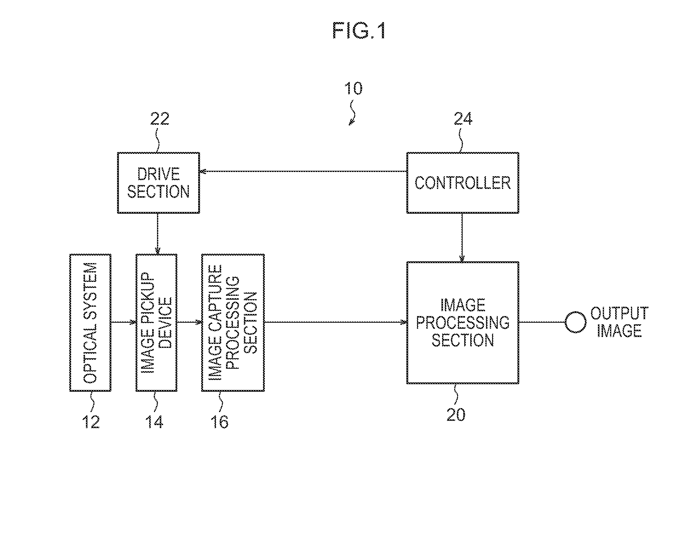
[0045]FIG. 1 is a schematic block diagram illustrating an imaging apparatus 10 according to the present exemplary embodiment. The imaging apparatus 10 is configured including an optical system 12, an image pickup device 14, an image capture processing section 16, an image processing section 20, a drive section 22, and a controller 24.

[0046]The optical system 12 is configured including for example a lens set configured from plural optical lenses, an aperture adjustment mechanism, a zoom mechanism, and an automatic focusing mechanism.

[0047]The image pickup device 14 is what is referred to as a 1-chip image pickup device configured by an image pickup device, such as for example a Charge Coupled Device (CCD) or a Complementary Metal Oxide Semiconductor (CMOS) containing plural photoelectric conversion elements arrayed in the horizontal direction and vertical direction, with a color filter disposed above the image pickup device.

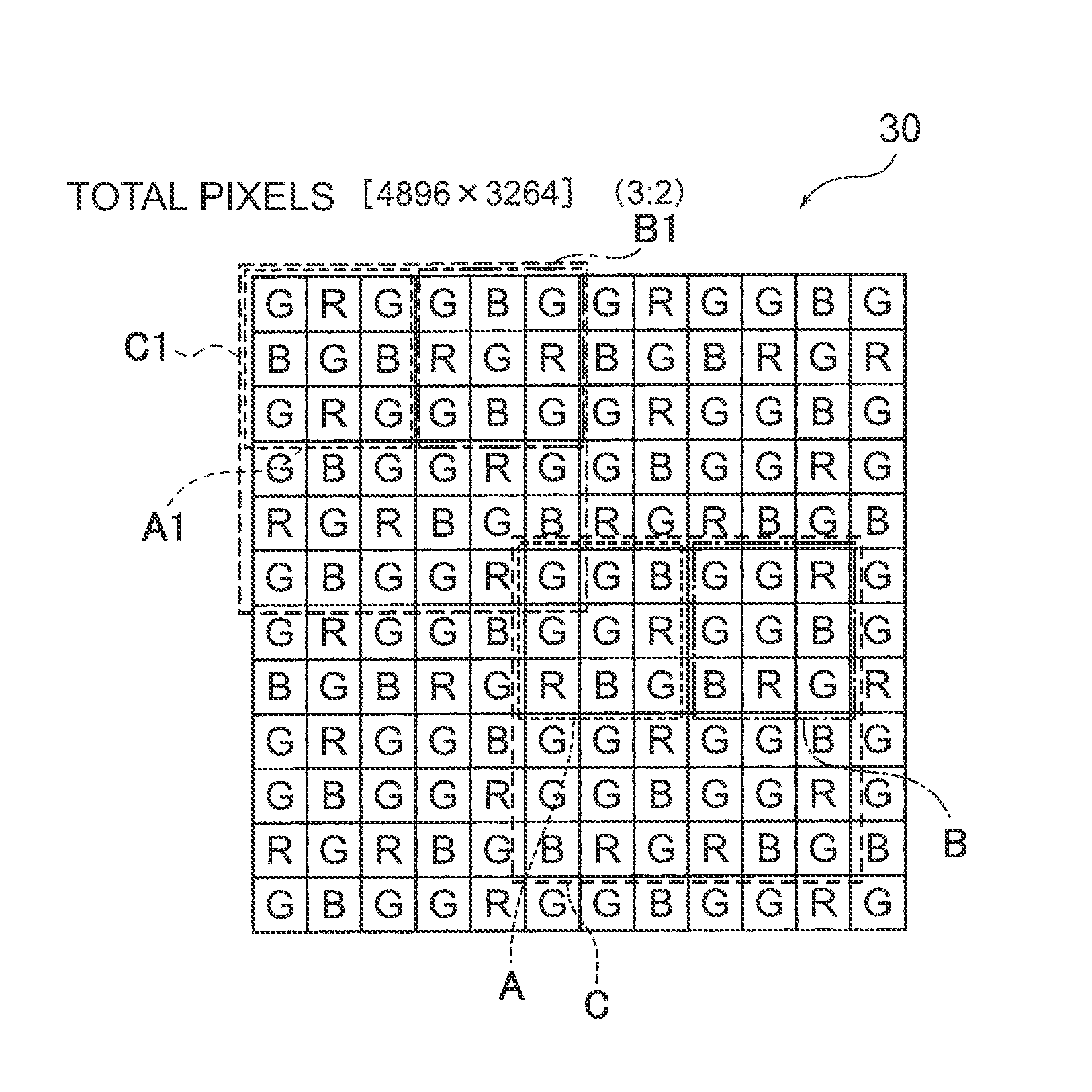
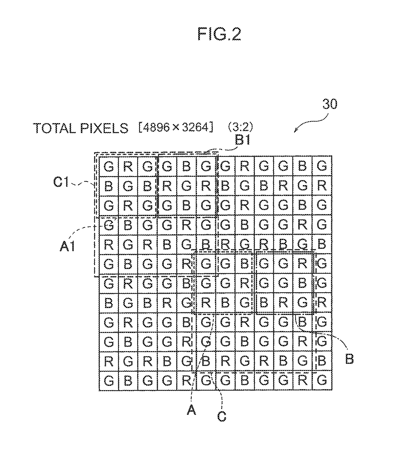
[0048]FIG. 2 illustrates a portion of a color filter 30...

second exemplary embodiment

[0093

[0094]Explanation next follows regarding a second exemplary embodiment of the present invention. Note that the same reference numerals are allocated to portions similar to those of the first exemplary embodiment, and detailed explanation thereof is omitted.

[0095]FIG. 6 illustrates a placement of light-blocking films 40A, 40B according to the present exemplary embodiment. A point of difference of the present exemplary embodiment to the first exemplary embodiment is the placement of the light-blocking films 40A, 40B.

[0096]As illustrated in FIG. 6, in the present exemplary embodiment, the light-blocking portions 40 are provided on each of the phase difference detection pixels of the upper side first array pattern A and second array pattern B out of the 2 first array patterns A and the 2 second array patterns B configuring the basic array pattern C, and are placed in all the basic array patterns C. Namely, in the example illustrated in FIG. 6, the light-blocking films 40A are place...

third exemplary embodiment

[0099

[0100]Explanation next follows regarding a third exemplary embodiment of the present invention. Note that the same reference numerals are allocated to portions similar to those of the above exemplary embodiment, and detailed description thereof is omitted.

[0101]FIG. 7 illustrates a placement of light-blocking films 40A, 40B according to the present exemplary embodiment. A point of difference of the present exemplary embodiment to the first exemplary embodiment is the placement of the light-blocking films 40A, 40B. Thinning driving is similar to that of the second exemplary embodiment.

[0102]As illustrated in FIG. 7, in the present exemplary embodiment, out of the 2 first array patterns A and 2 second array patterns B configuring the respective basic array patterns C, the light-blocking portions 40 are provided on 2 phase difference detection pixels on one diagonal of the 2×2 pixels at the top left of the first array pattern A that is disposed at the top left, and are placed in a...


PUM


Abstract

The precision of phase difference AF control is raised.An image pickup device includes a color filter that is provided with repeatedly disposed basic array patterns configured with a first array pattern and a second array pattern disposed symmetrically about a point, wherein the first array pattern includes a first filter placed over 2×2 pixels at the top left and a pixel at the bottom right of a 3×3 square array, a second filter placed over a right end pixel of a vertical direction center line of the square array and over a left end pixel a lower edge line, and a third filter placed over a pixel at the right end of the vertical direction upper edge line of the square array and over a center pixel of the lower edge line, and the second array pattern has the same placement of the first filter as that in the first array pattern and has a placement of the second filter and a placement of the third filter swapped over therefrom; and phase difference detection pixels that are placed at positions corresponding to 2 pixels that are adjacent in the horizontal direction out of the 2×2 pixels of at least one side of the upper side or lower side disposed first and second array patterns out of the 2 first array patterns and the 2 second array patterns configuring the basic array pattern.

Description

CROSS-REFERENCE TO RELATED APPLICATIONS[0001]This application is a continuation application of International Application No. PCT / JP2012 / 056595, filed Mar. 14, 2012, the disclosure of which is incorporated herein by reference in its entirety. Further, this application claims priority from Japanese Patent Application No. 2011-066632, filed Mar. 24, 2011, Japanese Patent Application No. 2011-163310, filed Jul. 26, 2011, and Japanese Patent Application No. 2011-289043, filed Dec. 28, 2012.BACKGROUND[0002]1. Technical Field[0003]The present invention relates to a color image pickup device, an imaging apparatus and a control program for an imaging apparatus, and in particular to a color image pickup device that includes phase difference detection pixels and to an imaging apparatus and a control program an imaging apparatus of the same.[0004]2. Related Art[0005]For solid state image pickup devices installed in imaging apparatuses such as digital cameras, there are those that, in order to r...

Claims


Application Information

Patent Timeline
Patent Type & Authority Patents(United States)
IPC IPC(8): H04N1/46
CPCH04N9/045H04N5/23212H04N9/077H04N1/02409H04N23/672H04N25/704H04N23/843H04N25/134
Inventor ENDO, HIROSHIIWASAKI, YOICHIAOKI, TAKASHIINOUE, KAZUKIHAYASHI, KENKICHITANAKA, SEIJIKAWAMURA, NORIKO
Owner FUJIFILM CORP
Learn More