Color imaging device

a color imaging and color technology, applied in the direction of picture signal generators, solid-state device signal generators, television systems, etc., can solve the problems of reducing resolution, reproducing accuracy, and coloring by the folding of high-frequency signals, so as to reduce the occurrence of false colors, and improve the effect of resolution

Active Publication Date: 2013-10-31
FUJIFILM CORP
View PDF3 Cites 10 Cited by
  • Summary
  • Abstract
  • Description
  • Claims
  • Application Information

AI Technical Summary

Benefits of technology

The present invention helps reduce false colors, achieve higher resolution, and simplify subsequent processing as compared to conventional random arrays.

Problems solved by technology

In this case, there is a problem of a reproduction characteristic of a high-frequency image signal, and there is an issue in which it is important that high-resolution is achieved by expanding a reproduction band while suppressing occurrence of color moire (false color) because, in the color imaging device, aliasing is easily generated in a captured image as compared with a monochrome imaging device.
In a primary color system Bayer array that is a color array that is widely used in the single-panel color imaging device, because green (G) pixels are arranged in a checkered pattern, and red (R) pixels and blue (B) pixels are arranged line-sequentially, there is a problem of reproduction accuracy when a high frequency signal is generated in the diagonal directions for the G signal and reproduction accuracy when a high frequency signal is generated in the horizontal and vertical directions for the R and B signals.
However, in this method, coloring by the folding of the high frequency signal can be reduced, but there is a problem that the resolution is reduced due to the adverse effect.

Method used


Image

  • Color imaging device
  • Color imaging device
  • Color imaging device

Examples


first embodiment

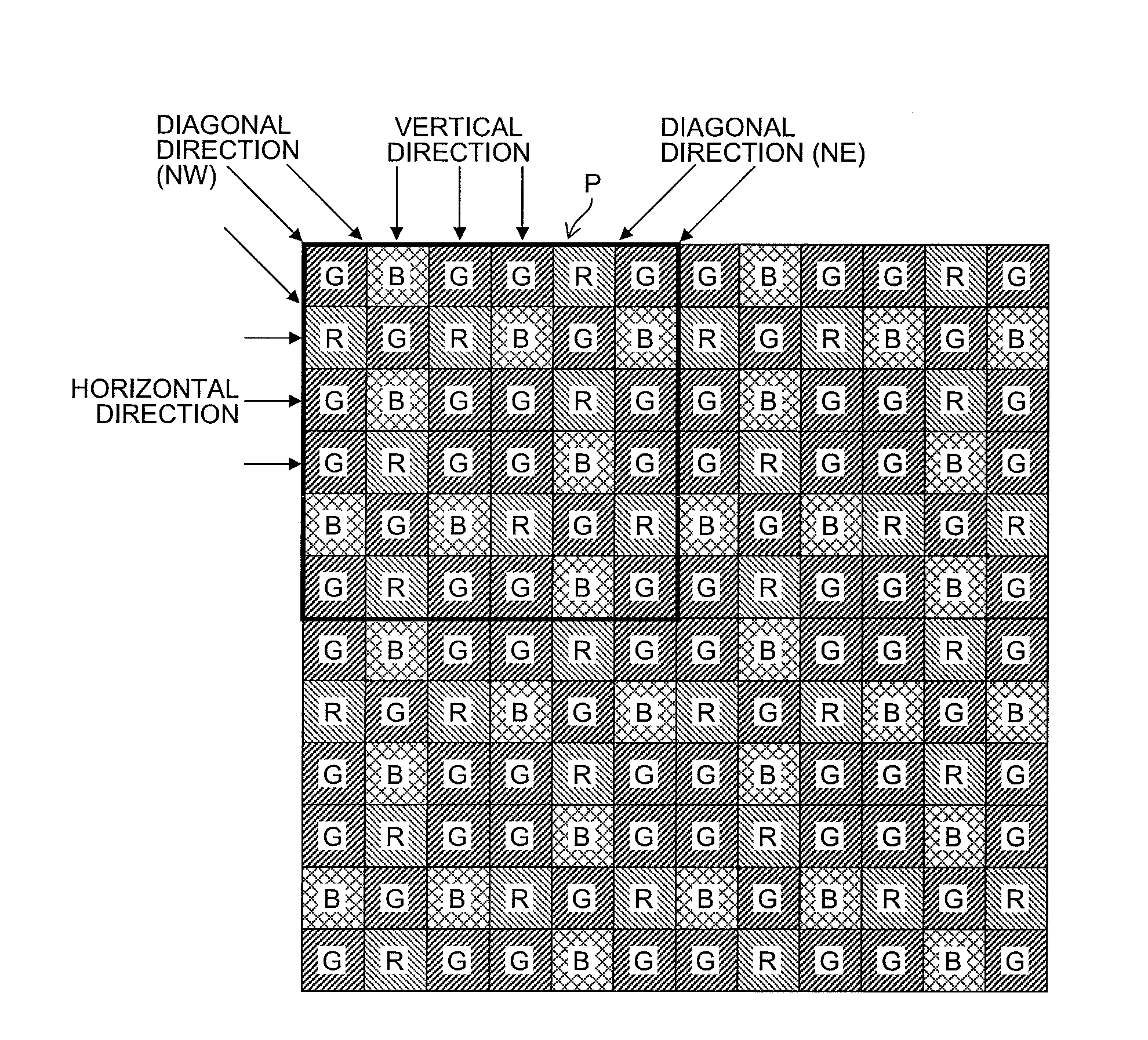
[0060]FIG. 1 is a diagram illustrating a first embodiment of a single-panel type color imaging device according to the present invention, and in particular, illustrating a color filter array of color filters that are provided in the color imaging device.

[0061]The color imaging device includes a plurality of pixels (not illustrated) that are constituted by photoelectric conversion devices that are arranged in the horizontal direction and the vertical direction (two-dimensional array), and color filters of a color filter array that is illustrated in FIG. 1 and arranged on a light receiving surfaces of each pixel, and any of the color filters of three primary colors of red (R), green (G), and blue (B) is arranged on each of the pixels.

[0062]Note that the color imaging device is not limited to a CCD (Charge Coupled Device) color imaging device, and may be another type of imaging device such as a CMOS (Complementary Metal Oxide Semiconductor) imaging device.

[0063]The color filter array o...

second embodiment

[0094]FIG. 6 is a diagram illustrating a second embodiment of the single-panel type color imaging device according to the present invention, and in particular, a color filter array of color filters that are provided in the color imaging device.

[0095]The color filter array of the color imaging device of the second embodiment has the same features as the features (1), (2), (3), (5), and (6) of the color filter array of the color imaging device of the first embodiment and a feature (7) that is not included in the color filter array of the color imaging device of the first embodiment. Note that the detailed description of the same portions as that of the first embodiment is omitted.

[0096](Feature (1))

[0097]The color filter array illustrated in FIG. 6 includes the basic array pattern P1 that is constituted by a square array pattern that corresponds to 3×3 pixels (pattern that is indicated by the thick frame), and the basic array pattern P1 is repeatedly arranged in the horizontal directi...

third embodiment

[0119]FIG. 9 illustrates a third embodiment of the single-panel type color imaging device according to the present invention, in particular, a color filter array of color filters that are provided in the color imaging device.

[0120]The color filter array of the color imaging device of the third embodiment includes the same features as the features (1), (2), (3), (5), and (6) of the color filter array of the color imaging device of the first embodiment and the feature (7) of the color filter array of the color imaging device of the second embodiment. Note that the detailed description of the same portions as that of the first embodiment and the second embodiment is omitted.

[0121](Feature (1))

[0122]In the color filter array illustrated in FIG. 9, a basic array pattern that is constituted by a square array pattern that corresponds to 3×6 pixels is repeatedly arranged in the horizontal direction and the vertical direction. In the basic array pattern, the G filters that are brightness sys...


PUM


Abstract

A color filter array includes a basic array pattern P1 constituted by a square array pattern corresponding to 3×3 pixels. In the color filter array, basic array pattern P1 is arranged in a horizontal direction and a vertical direction repeatedly. G filters that are brightness system pixels are arranged at the four corners and the center, that is, arranged on the both diagonal lines. The G filters are in each line of horizontal, vertical, and diagonal directions of the color filter array, and the color filter array includes a square array that corresponds to 2×2 pixels that are constituted by the G filters. A ratio of the number of G pixels that help most to obtain a brightness signal of the basic array pattern P1 is greater than each ratio of the number of R pixels and the number of B pixels that correspond to the color other than G.

Description

CROSS-REFERENCE TO RELATED APPLICATIONS[0001]This application is a continuation application and claims the priority benefit under 35 U.S.C. §120 of PCT Application No. PCT / JP2012 / 053775 filed on Feb. 17, 2012 which application designates the U.S., and also claims the priority benefit under 35 U.S.C. §119 of Japanese Patent Applications No. 2011-034627 filed on Feb. 21, 2011, No. 2011-162415 filed on Jul. 25, 2011 and No. 2011-286005 filed on Dec. 27, 2011 which applications are all hereby incorporated by reference in their entireties.TECHNICAL FIELD[0002]The present invention is related to a color imaging device, and in particular, to a color imaging device that can reduce occurrence of color moire and achieve high resolution.BACKGROUND ART[0003]Because an output image of a single-panel color imaging device is a RAW image (mosaic image), a multi-channel image is obtained by processing to interpolate a pixel of a missing color from the surrounding pixel (synchronization processing an...

Claims


Application Information

Patent Timeline
Patent Type & Authority Applications(United States)
IPC IPC(8): H04N9/04H04N23/12
CPCH04N9/045H04N2209/045H04N25/134
Inventor HAYASHI, KENKICHITANAKA, SEIJIKAWAI, TOMOYUKI
Owner FUJIFILM CORP
Why Eureka
Try Eureka