Lighting apparatus
a technology of lighting apparatus and light source, which is applied in the direction of lighting and heating apparatus, lighting source combinations, instruments, etc., can solve the problems of further examination and achieve the effect of easy control
- Summary
- Abstract
- Description
- Claims
- Application Information
AI Technical Summary
Benefits of technology
Problems solved by technology
Method used
Image

Examples
embodiment 1
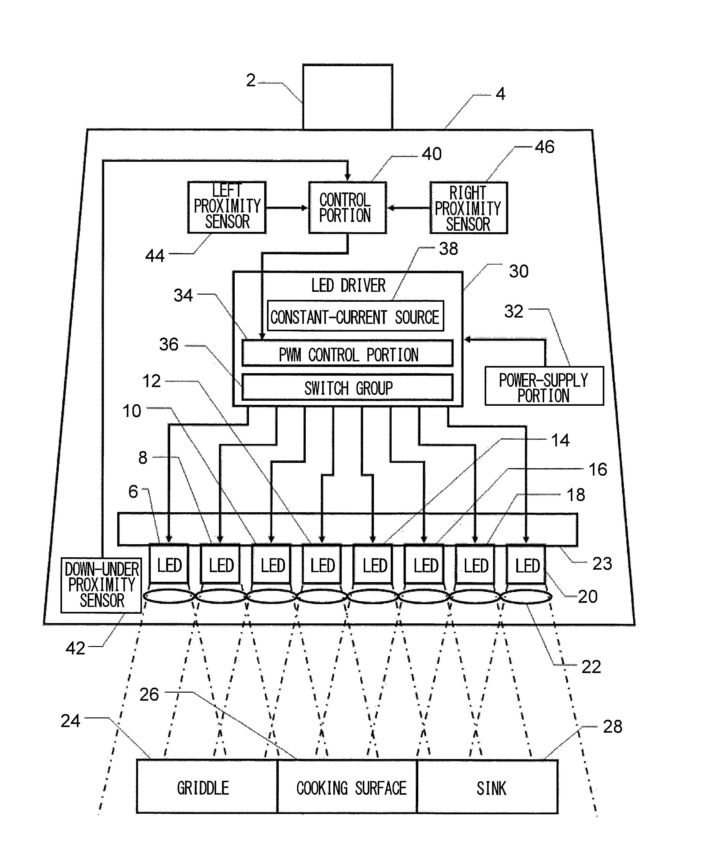
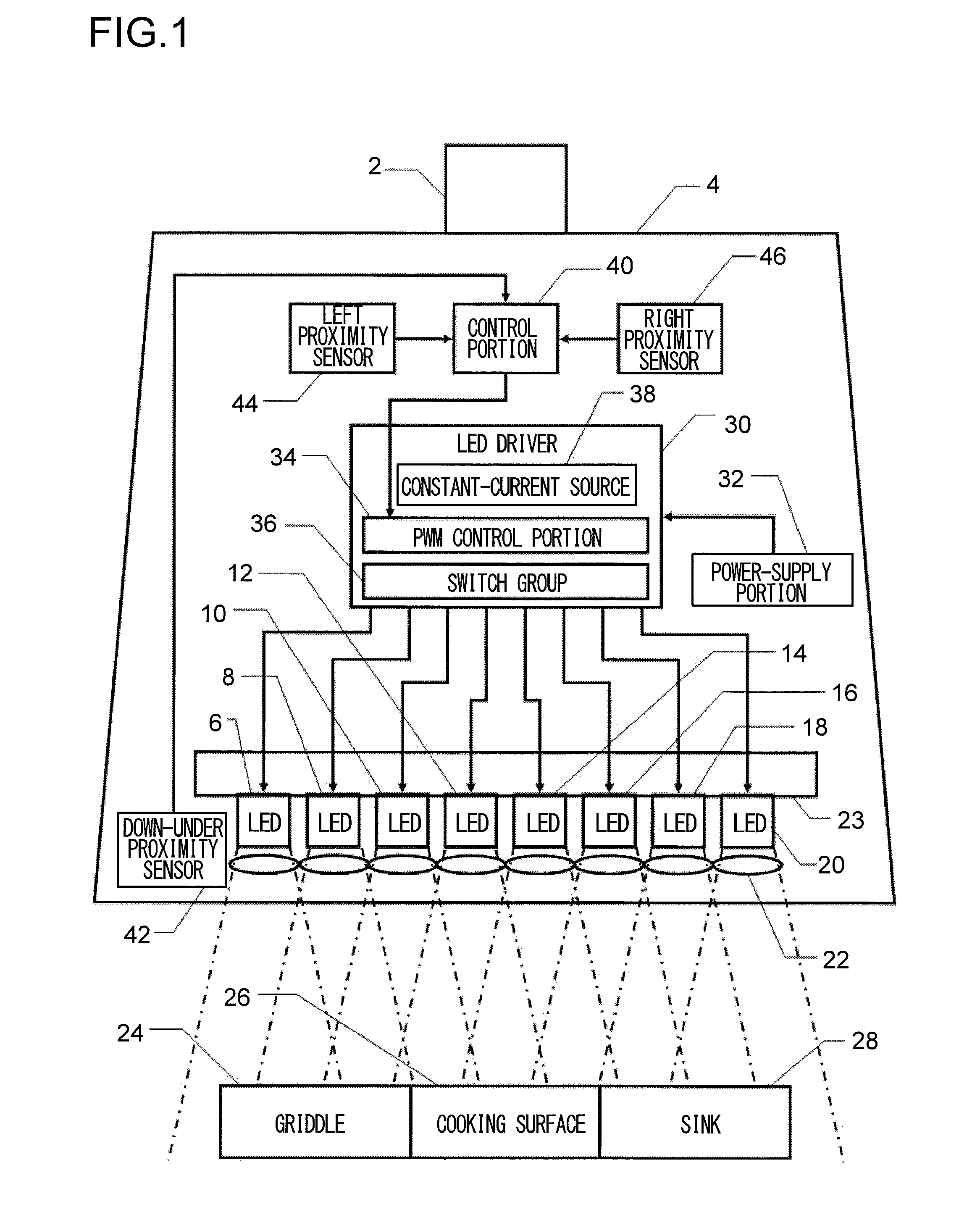
[0041]FIG. 2 is a circuit block diagram in Embodiment 1 in FIG. 1; portions corresponding to FIG. 1 are indicated by the same reference numbers and description is skipped unless necessary. The power supply portion 32 lowers an alternating voltage from a power line 48 by means of a transformer 50; rectifies the alternating voltage by means of a full-wave rectifier 52; smoothes the voltage by means of an electrolytic capacitor 54; and supplies the voltage to a direct current power supply circuit 56. Here, a structure may be employed, in which the transformer 50 is omitted; and the voltage is directly supplied to the full-wave rectifier 52 from the power line 48. Between the d.c. power supply circuit 56 and ground, a group of white light LEDs 6, 58, and 60, a switch device 62 and a constant-current source 64 are connected in series. In parallel with this, between the d.c. power supply circuit 56 and ground, a group of white light LEDs 8, 66, and 68, a switch device 70 and a constant-cu...
embodiment 2
[0052]As a result of the above structure, even without the light collection lens array 22, it is possible to efficiently shine the illumination light onto the kitchen utensils such as the griddle 24, the cooking surface 26, the sink 28 and the like that are below the lighting apparatus 104 and need the lighting. On substantially a center portion 101 of the bent shape of the white light LEDs 106 to 120 and the heat radiation plate 123, the light from all the white light LED groups concentrates, so that if there is an ingredient or a dish that the user wants to look in a bright state, it is sufficient to lift them to the center portion 101. Here, in Embodiment 2, the surface on which the white light LEDs 106 to 120 are disposed is part of a spherical surface; as a result of this, the light emission center axes of the white light LED groups concentrate on the center portion 101; however, to perform the disposition such that the light emission center axes of the white light LED groups a...
embodiment 3
[0060]Here, in the case of Embodiment 3, in a case of night light turning-on, all the white light LED groups are turned off, while the yellow light LED groups are turned on at a small duty cycle. Besides, in the case of changing the lighting brightness, to darken the lighting as a whole, automatic control is performed, in which the duty cycle of the white light LED group is made smaller than the duty cycle of the yellow light LED group such that a yellowish color prevails as a whole; on the other hand, to brighten the lighting as a whole, automatic control is performed, in which the duty cycle of the white light LED group is made larger than the duty cycle of the yellow light LED group such that a whitish color prevails as a whole. According to this, by sensuously approximating a color temperature change due to a brightness change of an incandescent lamp and a color temperature change during day time and dusk, a natural brightness change is performed.
[0061]FIG. 9 is a block diagram ...
PUM
 Abstract
Description
Claims
Application Information
 - R&D
- Intellectual Property
- Life Sciences
- Materials
- Tech Scout
- Unparalleled Data Quality
- Higher Quality Content
- 60% Fewer Hallucinations
Browse by: Latest US Patents, China's latest patents, Technical Efficacy Thesaurus, Application Domain, Technology Topic, Popular Technical Reports.
© 2025 PatSnap. All rights reserved.Legal|Privacy policy|Modern Slavery Act Transparency Statement|Sitemap|About US| Contact US: help@patsnap.com