
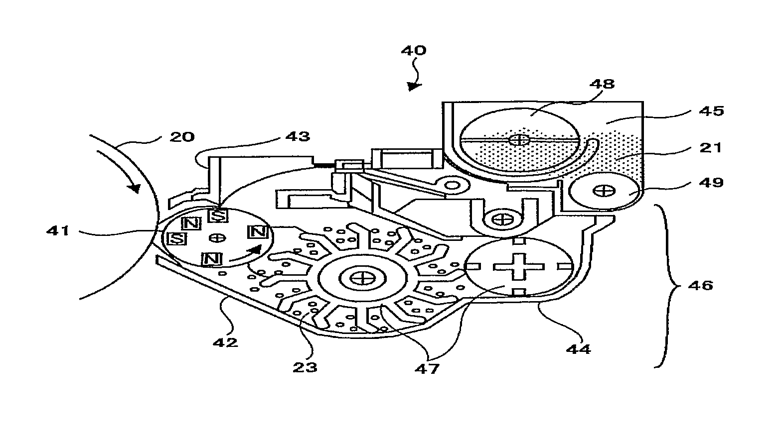
Carrier, developer, image forming method and process cartridge

a technology of developer and carrier, applied in the field of carrier, a developer, an image forming method and a process cartridge, can solve the problems of short operating life, difficult implementation of the related proposed carrier, poor developing ability, etc., and achieves excellent granularity, less occurrence of carrier adhesion and background smear, and long durability.

Active Publication Date: 2014-05-20
RICOH KK
View PDF23 Cites 1 Cited by
  • Summary
  • Abstract
  • Description
  • Claims
  • Application Information

AI Technical Summary

Benefits of technology

[0017]An object of the present invention is to solve the foregoing conditional problems and to provide a carrier and a developer which has fewer occurrences of carrier adhesion, excellent granularity, fewer occurrences of background smears, and higher durability, as well as to provide an image forming method using the developer and a process cartridge using the developer.
[0027]As magnetic binding force (Fm) applied to the carrier is proportional to cubic root of radius (r) of the carrier, minimizing the particle diameter of the carrier will drastically reduce the magnetic binding force proportionally to the cubic root of the particle diameter, causing higher occurrence of carrier adhesion.
[0060]According to the present invention, it is possible to provide a carrier and a developer, which have less occurrence of carrier adhesion and background smear, excellent granularity and longer durability, and the present invention can provide an image forming method, which uses the developer, and a process cartridge.

Problems solved by technology

For example, Patent Literature 1 proposes a magnetic carrier made of ferrite particles with spinel structures and an average particle diameter of less than 30 μm, however, the proposed carrier is not coated with resin and is used under low-electric field applied thereon, and has disadvantages in that it has poor developing ability and, because its is not coated with resin, it has a short operating life.
However, the related proposed carrier having small particle diameters has disadvantages in that carrier adhesion easily occurs, causing occurrences of image bearing member flaws and fixing roller flaws, thus implementation of the related proposed carriers is difficult.
In particular, when a carrier having an average particle diameter of less than 32 μm is used, the carrier surface texture will be drastically improved, and a high image quality can be obtained, however, there is a problem wherein carrier adhesion occurs very easily.(Patent Literature 1;) Japanese Patent Application Laid-Open No. 58-144839(Patent Literature 2;) Japanese Patent No. 3029180

Method used


Image

  • Carrier, developer, image forming method and process cartridge
  • Carrier, developer, image forming method and process cartridge
  • Carrier, developer, image forming method and process cartridge

Examples


production example 1

[0170]Silicone resin solution (solid content of 20% by mass): 75 parts

(SR2411, manufactured by DOW CORNING TORAY SILICON CO., LTD.)

[0171]Acrylate resin solution (solid content of 50% by mass): 10 parts

(Hitaroide3001, Manufactured by Hitachi Chemical Co., Ltd.)

[0172]Toluene: 100 parts

[0173]Butyl cellosolve: 100 parts

[0174]In order to make resin coating layer forming solution, the components stated above are mixed and fused with a homomixer for 10 minutes. The core material particles (A) in Table 1 were used, the surface of the core material particles are coated with resin coating layer forming solution with a Spilacoater (manufactured by OKADA SEIKO CO., LTD), forming the layer of 0.3 μm in thickness under the condition wherein temperature is 55° C. and forming rate is 30 g / minute. And then the particles are dried. The layer thickness is controlled with the amount of the solution. The carrier obtained from the previous process is then burned in an electric furnace at temperature of 1...

production example 2

[0177]All conditions were the same as those in Production Example 1, except that the core material particles B in Table 1 were used, and a carrier was obtained.

production example 3

[0178]All conditions were the same as those in Production Example 1, except the core material particles C in Table 1 were used, and a carrier was obtained.


PUM

PropertyMeasurementUnit
weight average particle diameteraaaaaaaaaa
diameteraaaaaaaaaa
diameteraaaaaaaaaa

Abstract

The present invention is to provide a carrier and a developer, which have fewer occurrences of carrier adhesion and background smear, excellent granularity and longer durability. The carrier comprises the core material particles having magnetism and resin coating layer covering the core material particles, and wherein the weight average particle diameters is in the range of 22 m to 32 m, the proportion of the weight average particle diameters relative to the number average particle diameter is in the range of 1.00 to 1.20, the content of particles having a diameter of 20 m or smaller is 7% by mass, the content of carrier particles having a diameter of 36 m or smaller is in the range of 90% by mass to 100% by mass, and the proportion of the particle density of the core material particles is in the range of 85% to 100% of the true density of the core material particles.

Description

TECHNICAL FIELD[0001]The present invention relates to a carrier, a developer, an image forming method and a process cartridge.BACKGROUND ART[0002]Developing processes of electrophotography are divided into a so-called one-component developing process using primarily a toner, and a so-called two-component developing process using a mixture of a toner with a glass bead, a magnetic carrier, or a coat carrier made of the glass bead or the magnetic carrier wherein their surface is coated with resin or the like.[0003]In such a two-component developing process, a carrier is used, and thus a two-component developer has a wider area frictionally charged to toner. In addition, the two-component developing process is more stable in charge property than the one-component developing process and is advantageous in providing high-quality images over a long period of time and has a high-ability of supplying a toner to areas to be developed. Thus, the two-component developing process is frequently u...

Claims


Application Information

Patent Timeline
Patent Type & Authority Patents(United States)
IPC IPC(8): G03G15/20G03G9/08G03G9/113G03G13/20
CPCG03G9/0819G03G9/1131G03G9/107G03G9/1139G03G9/1137G03G9/1136G03G9/0823G03G9/1135G03G9/0821G03G15/20G03G9/1085G03G9/108G03G9/1133G03G9/1087
Inventor NAGAYAMA, MASASHIYAMAGUCHI, KIMITOSHIIMAHASHI, NAOKI
Owner RICOH KK
Learn More