Supercharge Your Innovation With Domain-Expert AI Agents!
Letterpress printing machine
What is Al technical title?
Al technical title is built by PatSnap Al team. It summarizes the technical point description of the patent document.
a printing machine and letterpress technology, applied in printing presses, rotary letterpress machines, printing, etc., can solve the problems of insufficient homogeneity of letterpress printing, insufficient homogeneity of printed patterns, and insufficient printing quality
Active Publication Date: 2014-05-20
KBA NOTASYS SA
View PDF44 Cites 4 Cited by
Summary
Abstract
Description
Claims
Application Information
AI Technical Summary
This helps you quickly interpret patents by identifying the three key elements:
Problems solved by technology
Method used
Benefits of technology
Benefits of technology
[0012]A particular aim of the present invention is to improve preciseness of the inking of the letterpress forme cylinder.
[0013]A further particular aim is to render maintenance of such printing machines easier.
Problems solved by technology
A particularity of letterpress printing, especially letterpress printing in rotary printing machines, resides in the fact that the inking of the letterpress printing forme is not perfectly homogeneous.
As a result, the printed pattern is not perfectly homogeneous and tends to create a sort of shadow effect on one side of the printed pattern where ink has accumulated, which can be a problem in terms of printing quality.
Inks which accumulates on the sides of the raised portions of the letterpress printing forme thus has to be wiped away by periodically cleaning the letterpress printing forme, which cleaning process inevitably takes some time and negatively affects the production efficiency.
A further problem resides in the fact that disassembling and mounting of the rollers of the inking system for cleaning or replacement purposes is tedious and requires disconnecting and connecting, respectively, the gear drives that couples the inking system to the other rotating parts of the printing machine.
Method used
Image
Click on the blue label to locate the original text in one second.
Reading with bidirectional positioning of images and text.
Examples
Embodiment Construction
[0020]The invention will be described in connection with an example of a sheet-fed numbering machine for numbering sheets carrying banknotes. It shall however be understood that the invention is not limited to sheet-fed printing machines and is equally applicable to web-fed printing machines. Similarly, the invention is applicable to letterpress printing machines in general, or any printing machine which makes use, at least partly, of a letterpress printing forme.
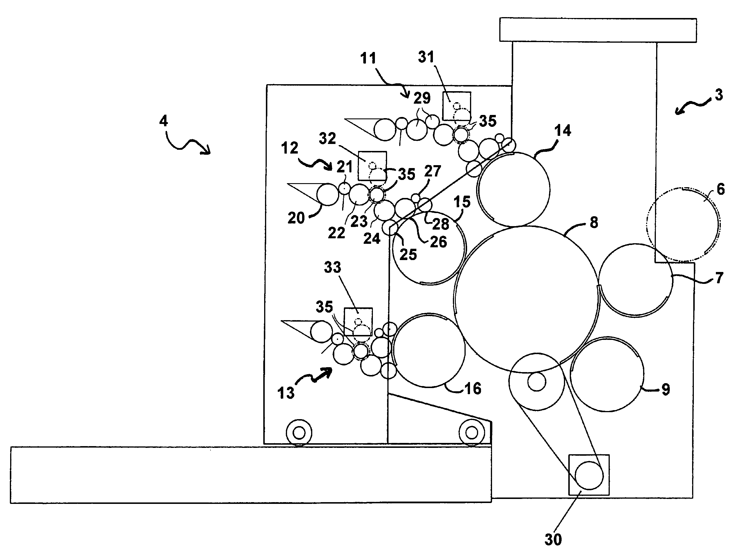
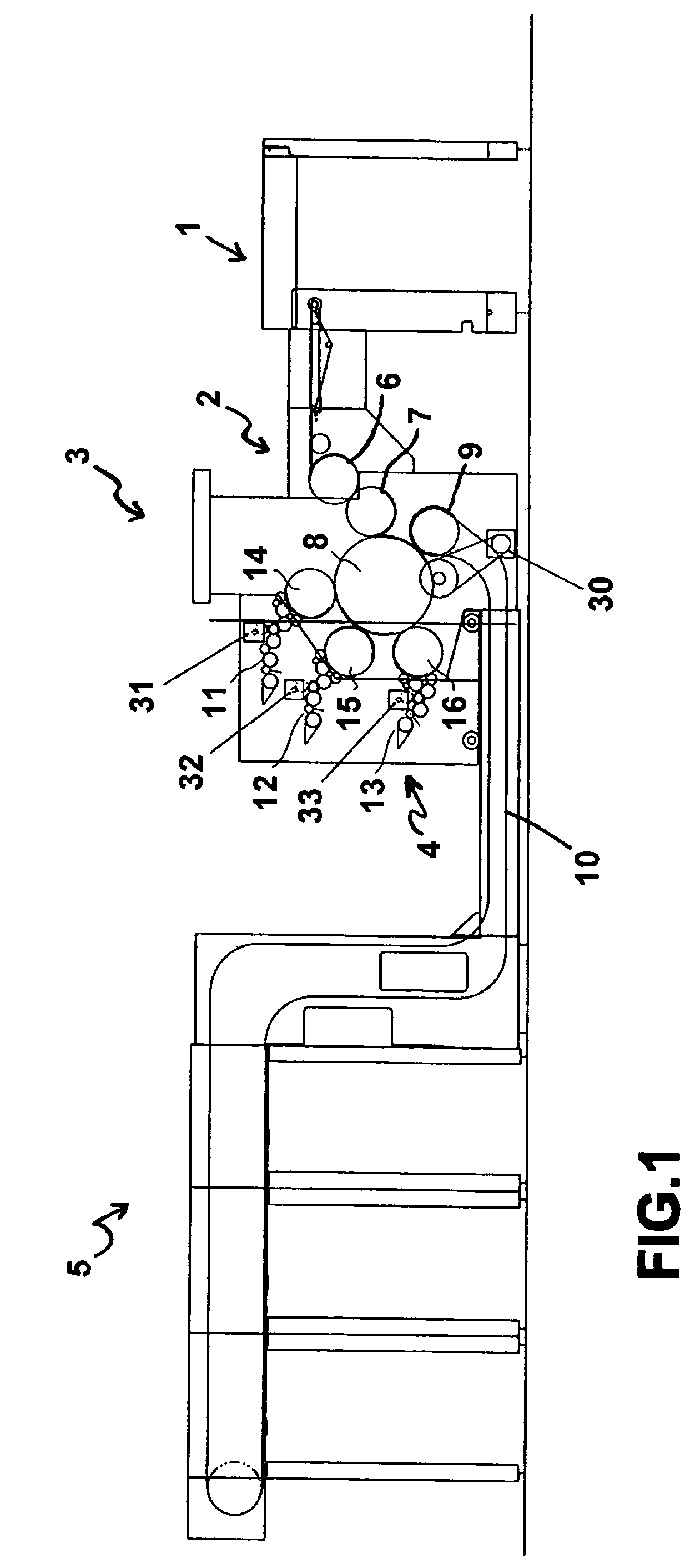
[0021]FIG. 1 shows a sheet-fed numbering machine assembly comprised of several units. The sheets which have previously been provided with a given number of prints arranged in matrix form and that shall be numbered are stored in a sheet feeder generally designated by 1. The sheets pass over the sheet feed table 2 and are transferred to a printing unit 3, by means of transfer cylinders 6 and 7. The sheets are taken up from transfer cylinder 7 by an impression cylinder 8 which cooperates with, in this example, three letterpres...
PUM
Abstract
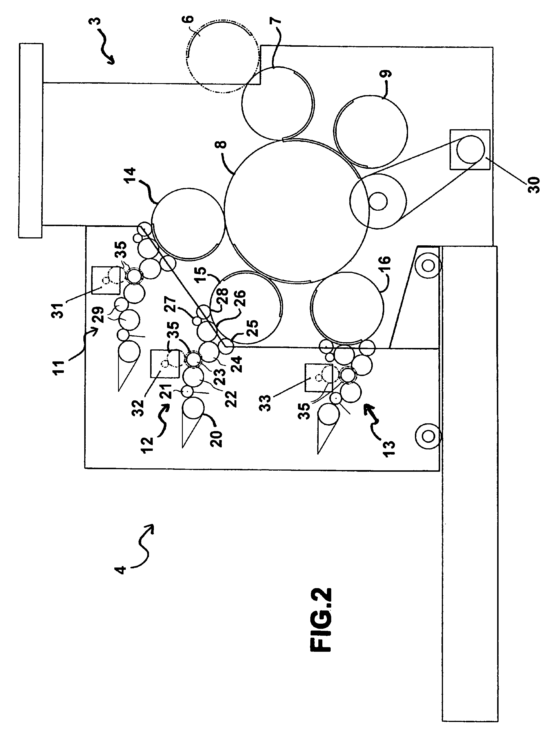
The letterpress printing machine includes an impression cylinder (8), at least one inking device (11, 12, 13) with an inking train comprising inking rollers (25, 26, 28) and at least one letterpress form cylinder (14, 15, 16) inked by said at least one inking device (11, 12, 13). The at least one letterpress form cylinder (14, 15, 16) is driven by first drive means (30), whereas the at least one inking device (11, 12, 13) is driven by second drive means (31, 32, 33), the second drive means (31, 32, 33) being mechanically independent from the first drive means (30). A control unit is coupled to the second drive means (31, 32, 33) to adjust a circumferential speed of the inking rollers (25, 26, 28) with respect to a circumferential speed of the letterpress form cylinder (14, 15, 16) so as to adjust deposition of ink by the inking device (11, 12, 13) on the letterpress form cylinder (14, 15, 16). At least one of letterpress form (14, 15, 16) cylinder is preferably a numbering cylinder for numbering printed sheets or webs.
Description
[0001]This application claims the benefits under 35 U.S.C. 119(a)-(d) or (b), or 365(b)of International Application No. PCT / IB2006 / 051651 filed May 23, 2006, and European Patent Application No. 05405363.2 filed Jun. 1, 2005.TECHNICAL FIELD[0002]The present invention generally relates to a letterpress printing machine, and more specifically to a letterpress numbering machine.BACKGROUND OF THE INVENTION[0003]Letterpress printing is a well-known printing process by which a rigid printing forme comprising raised portions corresponding to the pattern to be printed is inked with a relatively viscous, pasty ink, the inked pattern being thereafter applied to the paper either directly by contacting the paper and the inked printing forme or indirectly by first inking a transfer medium (or blanket) and thereafter applying this transfer medium to the paper.[0004]Letterpress printing is to be distinguished from flexography (which printing process also falls under the category of relief printing)...
Claims
Application Information
Patent Timeline
Application Date:The date an application was filed.
Publication Date:The date a patent or application was officially published.
First Publication Date:The earliest publication date of a patent with the same application number.
Issue Date:Publication date of the patent grant document.
PCT Entry Date:The Entry date of PCT National Phase.
Estimated Expiry Date:The statutory expiry date of a patent right according to the Patent Law, and it is the longest term of protection that the patent right can achieve without the termination of the patent right due to other reasons(Term extension factor has been taken into account ).
Invalid Date:Actual expiry date is based on effective date or publication date of legal transaction data of invalid patent.
