
Impact absorbing device for vehicle

a technology for impact absorption and vehicles, which is applied in the direction of elastic dampers, superstructure subunits, bumpers, etc., can solve the problems of increasing damages to drivers and passengers, and achieve the effects of reducing vehicle deformation, effective discharging crash energy, and improving passenger safety

Active Publication Date: 2014-05-13
HYUNDAI MOTOR CO LTD
View PDF8 Cites 13 Cited by
  • Summary
  • Abstract
  • Description
  • Claims
  • Application Information

AI Technical Summary

Benefits of technology

[0017]Various aspects of the present invention are directed to providing an impact absorbing device for a vehicle having advantages of effectively distributing crash energy to a side member and other portions of a vehicle body to reduce deformation of the vehicle body and improve safety of a passenger when an outer portion of the side member of a vehicle in a traverse direction of the vehicle has a front offset crash into a person, an object, or another vehicle.
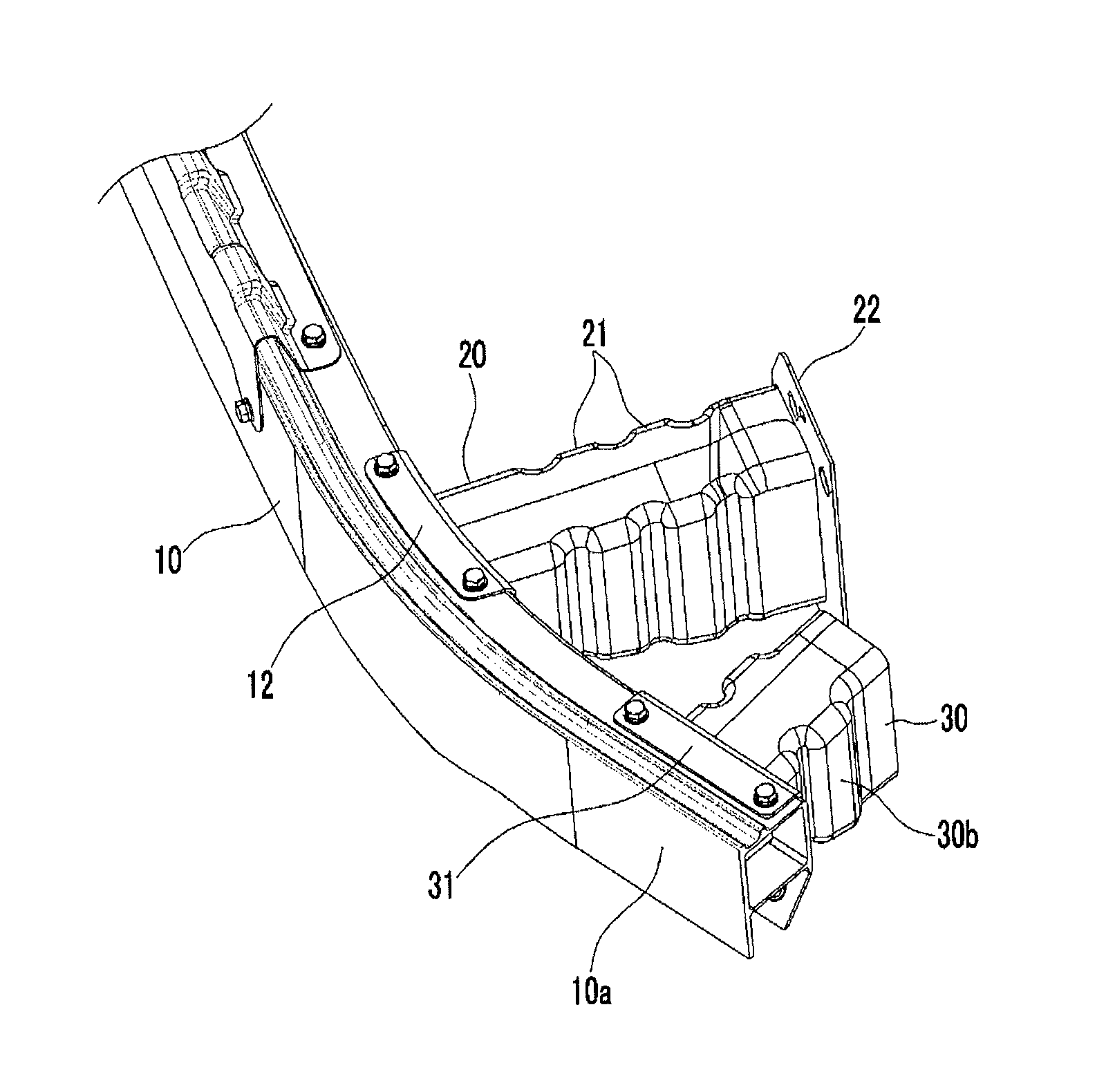
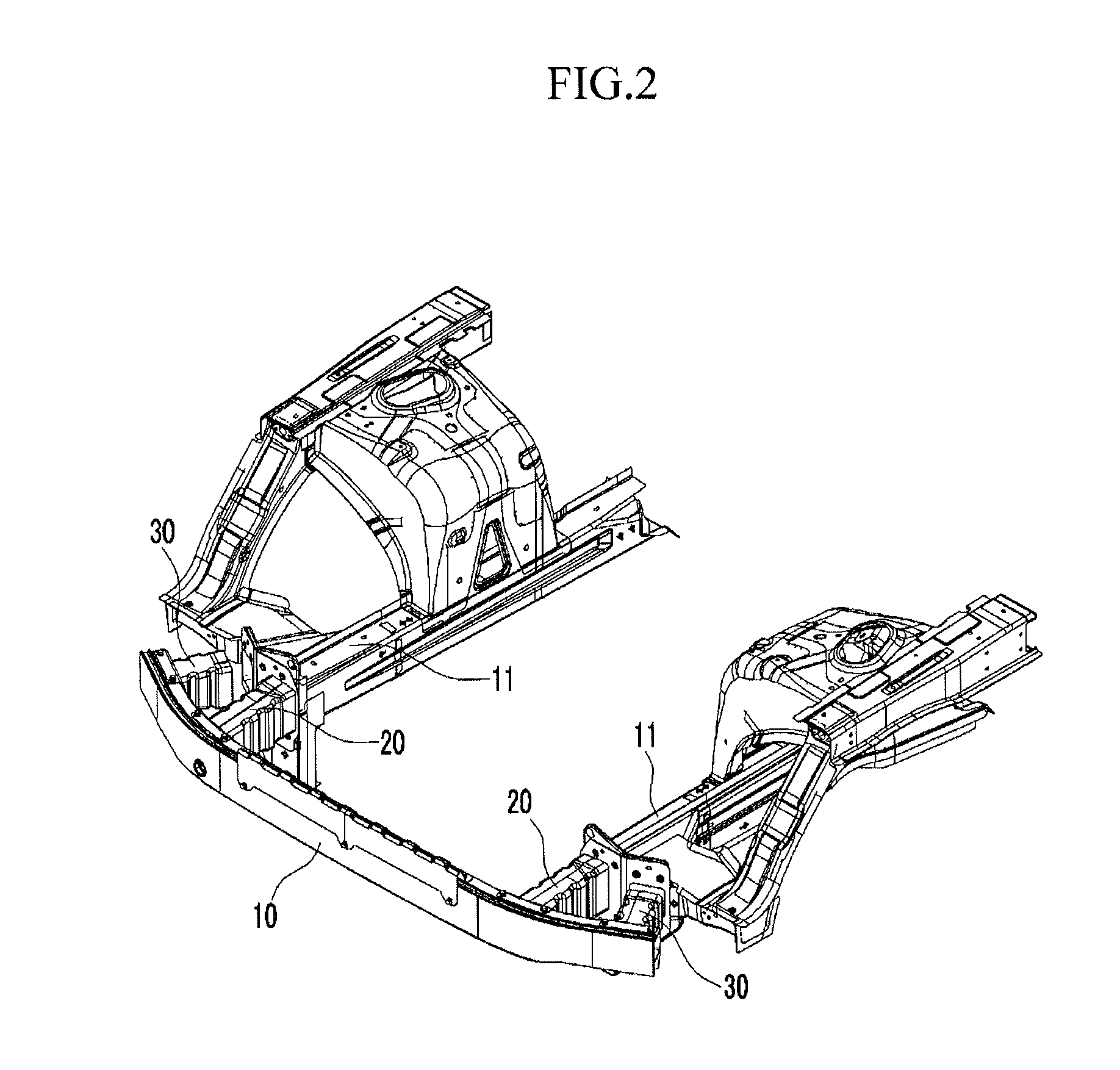
[0028]According to the impact absorbing device for the vehicle according to the exemplary embodiment of the present invention, the side crash boxes are mounted at both outer portions of the bumper beam positioned at outer sides of the side members in the traverse direction to the vehicle, thereby effectively responding to the front offset crash of the vehicle.
[0029]That is, the side crash boxes are mounted toward the connecting member between the side member and the fender apron member at both outer portions of the bumper beam, so that, in a case where the vehicle has an offset crash into a person, an object, or another vehicle at both outer portions of the bumper beam, the side crash boxes receive crash energy and are pushed toward the connecting member to be deformed, and primarily absorbs the crash energy during the process, thereby reducing the crash energy.
[0030]Further, the crash energy fails to be absorbed in the side crash boxes is transmitted to the side member and the fender apron member through the connecting member to be distributed to other portions of the vehicle body, so that it is possible to effectively reduce crash damage of the vehicle body due to concentration of the crash energy.
[0031]In addition, the crash energy is effectively distributed to other portions of the vehicle body through the side crash boxes as described above, so that an amount of transmission of the crash energy transmitted to a vehicle room is decreased, thereby reducing crash injury to a passenger.
[0032]Moreover, since the side crash boxes are mounted to be spaced from the connecting member at a predetermined interval, only the bumper beam is deformed while the crash energy is completely absorbed by the bumper beam, and the side crash boxes maintain their original shapes without crashing into the connecting member in a case where both outer portions of the bumper beam of the vehicle has a front offset crash at a lower speed.

Problems solved by technology

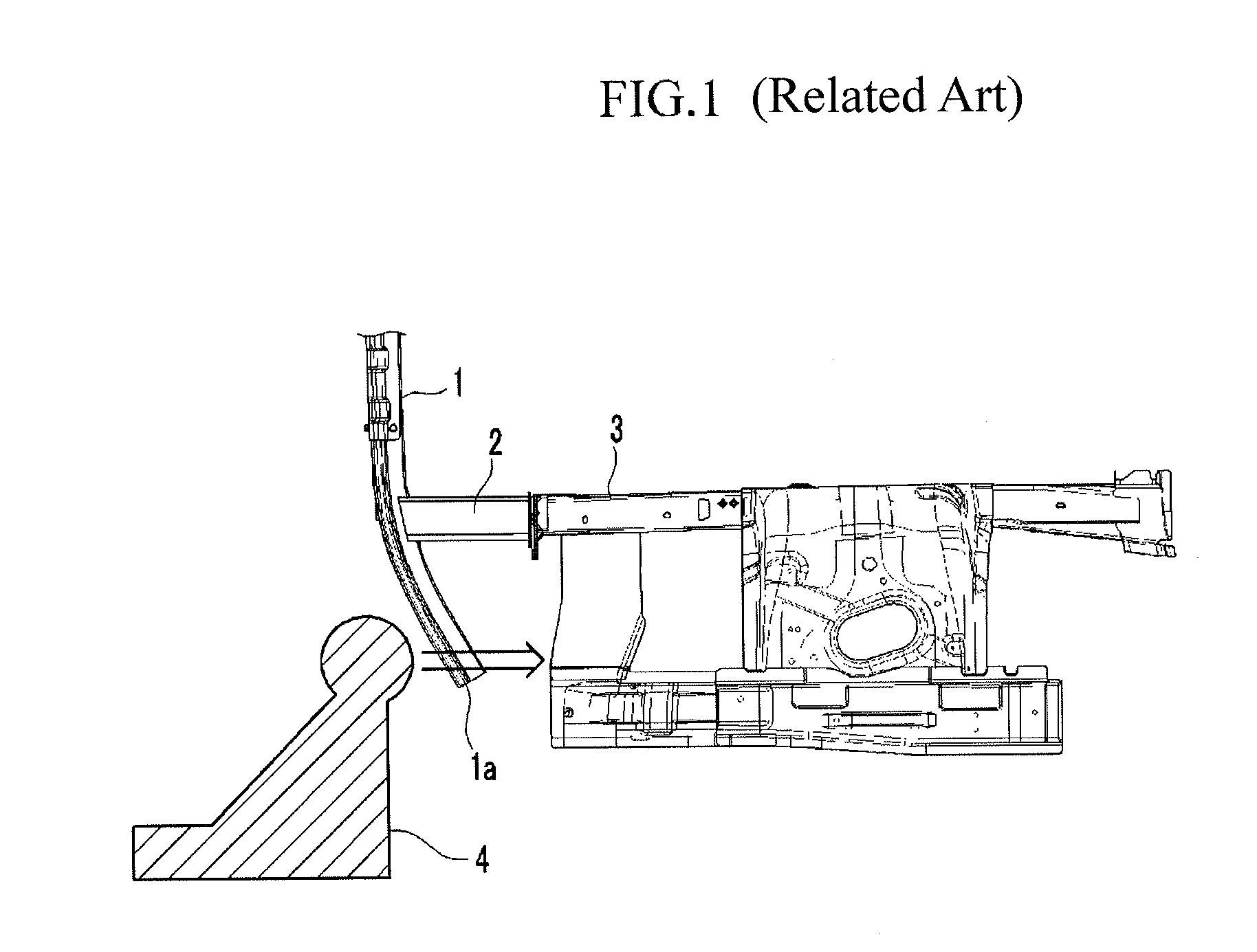
Accordingly, the barrier 4 hits both outer portions 1a of the bumper beam 1 to be crashed into a tire part of the vehicle, and the tire is pushed into a vehicle room by the barrier 4 to hit a lower portion of a driver's seat, thereby increasing damages to a driver and a passenger.

Method used


Image

  • Impact absorbing device for vehicle
  • Impact absorbing device for vehicle
  • Impact absorbing device for vehicle

Examples


Embodiment Construction

[0043]Reference will now be made in detail to various embodiments of the present invention(s), examples of which are illustrated in the accompanying drawings and described below. While the invention(s) will be described in conjunction with exemplary embodiments, it will be understood that the present description is not intended to limit the invention(s) to those exemplary embodiments. On the contrary, the invention(s) is / are intended to cover not only the exemplary embodiments, but also various alternatives, modifications, equivalents and other embodiments, which may be included within the spirit and scope of the invention as defined by the appended claims.

[0044]Hereinafter, an exemplary embodiment of the present invention will be described in detail with reference to the accompanying drawings.

[0045]Referring to FIG. 2, an impact absorbing device for a vehicle according to an exemplary embodiment of the present invention includes a bumper beam 10 extending in a traverse direction of...


PUM


Abstract

An impact absorbing device for a vehicle may include a bumper beam disposed to extend in a traverse direction of a vehicle, a side member extending in a longitudinal direction of the vehicle and disposed at a lateral side of the vehicle in the traverse direction thereof, a crash box connecting the bumper beam in the longitudinal direction of the vehicle to the side member, a fender apron member disposed at outer sides of the side member in the traverse direction of the vehicle, a connecting member connecting the fender apron member and the side member, and a side crash box of which a front tip end may be mounted to an outer portion of the bumper beam positioned at an outer direction of the side member in the traverse direction of the vehicle, and of which a rear tip end may be disposed to be spaced apart from the connecting member at a predetermined interval therebetween.

Description

CROSS-REFERENCE TO RELATED APPLICATION[0001]The present application claims priority to Korean Patent Application No. 10-2012-0097311 filed on Sep. 3, 2012, the entire contents of which is incorporated herein for all purposes by this reference.BACKGROUND OF THE INVENTION[0002]1. Field of the Invention[0003]The present invention relates to an impact absorbing device for a vehicle, and more particularly, to an impact absorbing device for a vehicle in which a side crash box is installed outside a crash box.[0004]2. Description of Related Art[0005]In general, an impact absorbing device for a vehicle is mounted on a front side and a rear side in a longitudinal direction of a vehicle so as to contribute to safety of passengers by absorbing impact when a vehicle crashes into a pedestrian, another vehicle, or an object and to simultaneously minimize deformation of a vehicle body.[0006]Referring to FIG. 1, an impact absorbing device for a vehicle in the related art includes bumper beams 1 man...

Claims


Application Information

Patent Timeline
Patent Type & Authority Patents(United States)
IPC IPC(8): B60R19/34
CPCB60R19/34B60R19/04B62D25/082B62D25/088F16F7/12B60R19/24
Inventor HAN, MIN, UKE
Owner HYUNDAI MOTOR CO LTD
Learn More