
Apparatus for enhancing the dynamic range of shockline-based sampling receivers

a technology of dynamic range and receiver, applied in the direction of resistance/reactance/impedence, instruments, transmission monitoring, etc., can solve the problems of limiting the dynamic range of vna, performance items are still an issue, affecting the accuracy of measurements, etc., and achieve the effect of reducing channel-to-channel isolation and enhancing the dynamic range of shockline-based sampling receivers

Active Publication Date: 2014-05-06
ANRITSU CO
View PDF22 Cites 19 Cited by
  • Summary
  • Abstract
  • Description
  • Claims
  • Application Information

AI Technical Summary

Benefits of technology

[0015]According to embodiments of the present invention, a technique is provided to enhance the dynamic range of shockline-based sampling receivers without experiencing the generation of spurious responses and the reduction in channel-to-channel isolation as in previous systems.
[0017]In one embodiment the bias voltage is selectable between a reverse-bias or negative voltage and a forward bias or positive voltage. The forward bias voltage is applied to turn off shocklines in channels that are not operating in order to reduce spurious generation and improve channel-to-channel isolation. In the limit of a strong forward or positive bias voltage, the incoming LO and its harmonics experience large ohmic losses along the shockline preventing gating pulses from forming. This accomplishes the same effect as turning off the sampler or the LO in one channel without the problems associated with prior-art approaches (i.e., transient problems are reduced and possible IF bandwidths are not affected). A reverse bias voltage is applied to turn on desired shocklines. In the reverse-bias or negative bias mode, the shockline diodes are typically in a reactive region, and falling edge compression can be reduced to improve overall performance.

Problems solved by technology

Two problems that arise in high frequency Vector Network Analyzers (VNA) that can affect the accuracy of measurements are intermodulation-product generation, created by the down-converters (which may include samplers), and inadequate channel to channel isolation that can limit the VNA's dynamic range.
Use of shock-line based samplers in VNA receivers improves performance in both of these (among other) categories but these performance items are still an issue.
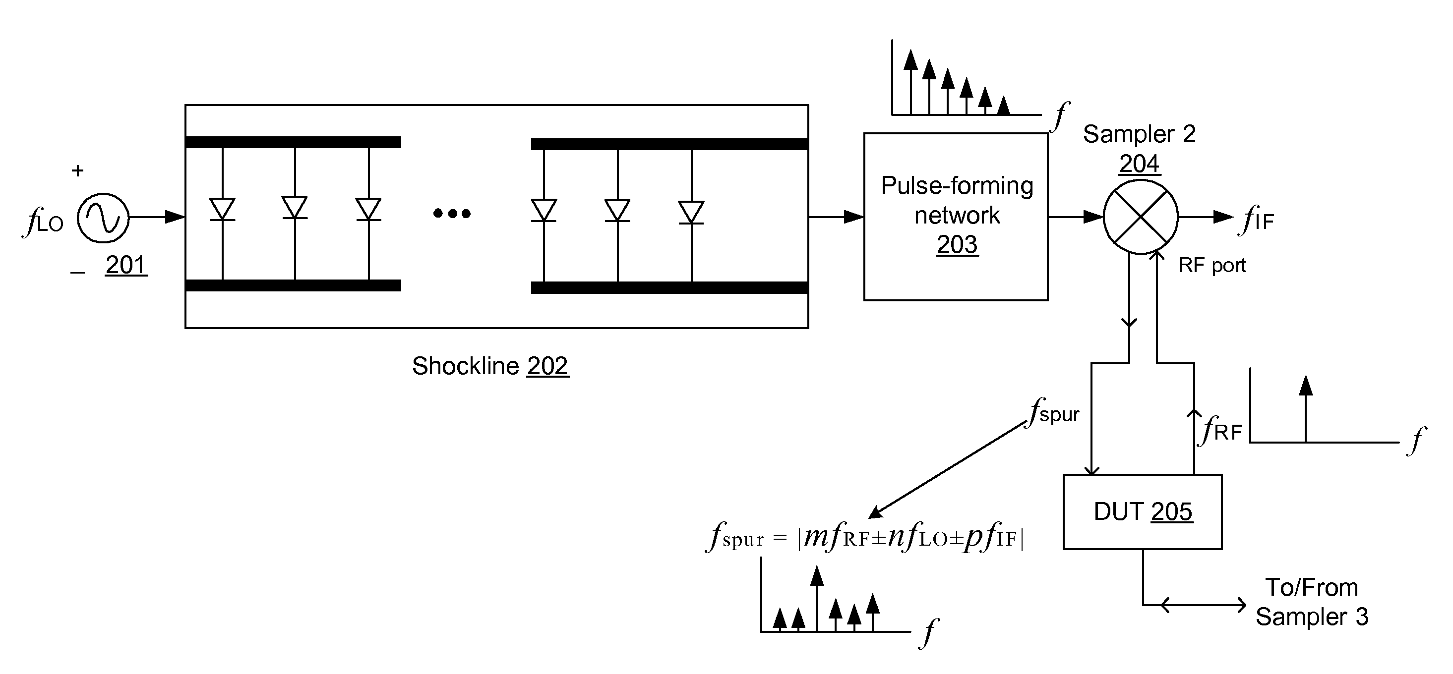
But the sampler is well known for generating spurious products that result when an RF signal undergoes partial reflection at the sampler's RF port.
In a VNA context, these spurious products emerge from the sampler's RF port and make their way to the device under test (DUT) to create measurement errors.
The rich harmonic content of a narrow sampling pulse mixes in the diodes of the sampler with these RF signals to generate spurious products.
This could lead to an unrealistic measurement due to the conversion of these spurious products creating an IF similar to that produced by the intended signals.
This could, however, be very expensive in a broadband system and could worsen the overall dynamic range of the system by introducing additional non-idealities, such as noise or compression.
While adding additional components as shown in FIG. 1 may improve isolation, such systems to improve isolation have drawbacks.
Multiple stages of filters, isolators, and amplifiers added to achieve sufficient isolation can significantly increase cost and power consumption, particularly in broadband systems.
The addition of isolation components and multiple amplifier stages can further worsen the overall dynamic range of the receiver.
This solution may require additional sampler power supply ports to accomplish the turn off and may reduce available intermediate frequency (IF) bandwidth due to loading.
But this technique can be complicated since high power levels at high frequencies are often involved in the LO which cannot be readily switched on and off.
There may also be the thermal-transient and power stability issues in trying to turn rapidly off and on LO power as would happen in a high-speed measurement system.
The DC bias voltage applied to the NLTL provides direct control over the falling-edge shockline compression, and thus the insertion loss and overall RF bandwidth of the sampler.
In the limit of a strong forward or positive bias voltage, the incoming LO and its harmonics experience large ohmic losses along the shockline preventing gating pulses from forming.

Method used


Image

  • Apparatus for enhancing the dynamic range of shockline-based sampling receivers
  • Apparatus for enhancing the dynamic range of shockline-based sampling receivers
  • Apparatus for enhancing the dynamic range of shockline-based sampling receivers

Examples


Embodiment Construction

[0025]FIG. 3 shows a vector network analyzer (VNA) with components included according to embodiments of the present invention. Source Generator 300 provides a source signal to power splitter 302. The power splitter splits the source signal into separate signals for driving test and reference channel samplers. Two test channels and two reference channels are utilized in the embodiment shown, but any number of channels may be used, depending on the design of the VNA. In each channel a nonlinear transmission line (NLTL), or shockline, receives the LO signal from the power splitter 302 and produces a pulse signal. The pulse signal is then used to gate a sampler 312-318.

[0026]Embodiments of the present invention in FIG. 3 include dynamic shock-line biasing circuit for enhancing the dynamic range of the sampling VNA. Each shockline is dynamically biased using a dynamic bias circuit 358-364. In one embodiment the bias voltage of the shockline is controlled to improve performance. The biasi...


PUM


Abstract

Shockline-based samplers of a vector-network analyzer (VNA) have enhanced dynamic range by using a dynamic bias network applied to the non-linear transmission lines (NLTLs) or shocklines. The bias voltage applied to the NLTL provides direct control over the falling-edge shockline compression, and thus the insertion loss and overall RF bandwidth of the sampler. Alternating between a forward bias voltage to turn off a shockline sampler when it is not needed and thereby reducing spurious generation and improving isolation can be alternatively applied with a reverse bias voltage to turn on the shockline sampler in a normal operation mode. By measuring the shockline output and providing feedback in the reverse-bias mode, the bias voltage can be dynamically adjusted to significantly increase the performance of the NLTL based sampler. In the presence of a strong positive bias voltage, the incoming LO and its harmonics experience large ohmic losses thus preventing gating pulses from forming in the shockline. The ohmic losses enable strong isolation between the LO sampling channels and will increase spectral purity at the VNA test ports.

Description

BACKGROUND[0001]1. Technical Field[0002]The present invention relates to apparatus for enhancing the dynamic range of shockline-based sampling receivers.[0003]2. Related Art[0004]Two problems that arise in high frequency Vector Network Analyzers (VNA) that can affect the accuracy of measurements are intermodulation-product generation, created by the down-converters (which may include samplers), and inadequate channel to channel isolation that can limit the VNA's dynamic range. Use of shock-line based samplers in VNA receivers improves performance in both of these (among other) categories but these performance items are still an issue. One example of the use of shockline samplers in a VNA and how they may be further enhanced to increase isolation is described in U.S. Pat. No. 7,088,111 entitled “Enhanced Isolation Between Sampling Channels In A Vector Network Analyzer,” by K. Noujeim.[0005]Shockline-based samplers, whether used in a VNA or other receivers to achieve very high frequen...

Claims


Application Information

Patent Timeline
Patent Type & Authority Patents(United States)
IPC IPC(8): H04B7/00
CPCG01R27/32
Inventor MARTENS, JONNOUJEIM, KARAM MICHAEL
Owner ANRITSU CO
Learn More