
Hierarchical control of tiered error recovery for storage devices

a technology of error recovery and storage device, applied in the field of error detection, can solve problems such as error bursts, inability to identify, and failure to achieve inline recovery

Inactive Publication Date: 2014-05-06
IBM CORP
View PDF36 Cites 9 Cited by
  • Summary
  • Abstract
  • Description
  • Claims
  • Application Information

AI Technical Summary

Benefits of technology

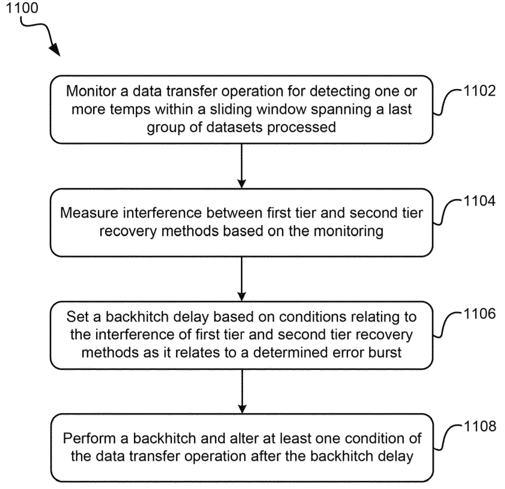
The patent describes a system and method for improving data transfer operations in a tape drive system. The system includes a read channel for performing data transfer operations, logic for monitoring the transfer operations for temperature and interference between recovery methods, and logic for setting a backhitch delay based on the interference. The method involves detecting temperature spikes and interference between recovery methods, setting a backhitch delay based on the interference, and performing a backhitch after the delay. The system can also include a computer program product for monitoring and measuring interference between recovery methods, setting a backhitch delay, and performing a backhitch after the delay. The technical effects of this patent include improved data transfer speed and accuracy, reduced latency, and improved overall performance of the tape drive system.

Problems solved by technology

In a field or test environment implementing a tape-based data storage system, situations may arise where successful inline recovery may still impact overall performance, as in the case of frequent error recovery known as an error burst.
Error bursts, which may include a large number of errors in a given time frame or in a given length of tape in a given direction, are not easily identified since no permanent errors occur and data continues to transfer across the host / drive interface.
Even if individual recovery is only transitory in nature, when it persists over long stretches of tape, these error bursts can lead to host command timeouts and excessive processing times that seriously degrade performance.
However, since each tier has a different context and scope, their respective persistence methods can come into conflict, which causes recovery issues that must be dealt with.

Method used


Image

  • Hierarchical control of tiered error recovery for storage devices
  • Hierarchical control of tiered error recovery for storage devices
  • Hierarchical control of tiered error recovery for storage devices

Examples


Embodiment Construction

[0026]The following description is made for the purpose of illustrating the general principles of the present invention and is not meant to limit the inventive concepts claimed herein. Further, particular features described herein can be used in combination with other described features in each of the various possible combinations and permutations.

[0027]Unless otherwise specifically defined herein, all terms are to be given their broadest possible interpretation including meanings implied from the specification as well as meanings understood by those skilled in the art and / or as defined in dictionaries, treatises, etc.

[0028]It must also be noted that, as used in the specification and the appended claims, the singular forms “a,”“an” and “the” include plural referents unless otherwise specified.

[0029]The following description discloses several preferred embodiments of magnetic storage systems, as well as operation and / or component parts thereof.

[0030]In one general embodiment, a tape ...


PUM

PropertyMeasurementUnit
wrap angleaaaaaaaaaa

Abstract

In one embodiment, a tape drive system includes a read channel configured for performing a portion of a data transfer operation, logic adapted for monitoring the data transfer operation for detecting one or more temps within a sliding window spanning a last group of datasets processed, logic adapted for measuring interference between first tier and second tier recovery methods based on the monitoring, logic adapted for setting a backhitch delay based on conditions relating to the interference of first tier and second tier recovery methods as it relates to a determined error burst, and logic adapted for performing a backhitch and altering at least one condition of the data transfer operation after the backhitch delay.

Description

BACKGROUND[0001]The present invention relates to error detection, and more particularly, this invention relates hierarchical control of tiered error recovery for tape storage device.[0002]Error detection and recovery is important to any system in which data passes from one point to another. Error detection and recovery is particularly important in the data storage industries, as users rely on the integrity of the stored data for everything from day to day operation to long term archiving. Tape drives require inline error recovery algorithms to recover errors during data processing.[0003]In a field or test environment implementing a tape-based data storage system, situations may arise where successful inline recovery may still impact overall performance, as in the case of frequent error recovery known as an error burst. Error bursts, which may include a large number of errors in a given time frame or in a given length of tape in a given direction, are not easily identified since no p...

Claims


Application Information

Patent Timeline
Patent Type & Authority Patents(United States)
IPC IPC(8): G11B5/09G11B27/36
CPCG11B2220/90G11B27/36G11B2020/183G11B20/18G11B15/20
Inventor NYLANDER-HILL, PAMELA R.OISHI, YUTAKAMASUDA, SETSUKO
Owner IBM CORP
Learn More