High-speed interface connector

a high-speed interface and connector technology, applied in the direction of coupling contact members, coupling device connections, two-part coupling devices, etc., can solve the problems of reducing convenience and being susceptible to external noise, and achieve the effect of reducing the degradation of the quality of differential signals

Inactive Publication Date: 2014-04-29
PANASONIC CORP
View PDF9 Cites 1 Cited by
  • Summary
  • Abstract
  • Description
  • Claims
  • Application Information

AI Technical Summary

Benefits of technology

[0009]Improvements in functionalities of host devices have increasingly improve quality of pictures and movies to be recorded, and storage capacity of memory cards have also been increasing in conjunction. However, as an increased data volume to be handled also increases time required for data transmission between a host device and a memory card and reduces convenience, it has been demanded for memory cards to be improved in speed for data transmission between a host device and a memory card as the storage capacity of memory cards increases.
[0010]There are several possible approaches in order to improve speed for transmission between a host device and a memory card. One of these is to improve a transmission rate of a signal transmission system for transmission with a host device via existing signal pins of a memory card. The conventional memory cards have employed a single-ended transmission system as a signal transmission system with a host device, and handled an increased storage capacity of the memory cards by improving the transmission rate.
[0013]Additionally providing dedicated pins used exclusively for differential transmission is one method of introducing the differential transmission system to memory cards that have performed signal transmission with a host device using the single-ended transmission system. When additionally providing new pins to an existing memory card, an area for newly provided pins is restricted. In addition, a memory card to be provided with new pins requires a pin arrangement such that when the memory card is inserted into a memory card socket, contact terminals of the memory card socket that are connected to the existing signal pins may not go wrong during insertion of the memory card even if the terminals are brought into contact with the new pins. Alternatively, the memory card requires a pin arrangement such that the new pins may not be brought into contact with the contact terminals of the memory card socket that are connected to the existing signal pins during insertion of the memory card into the memory card socket.
[0016]Thus, an object of the present invention is to provide a high-speed interface connector providing connection for a differential transmission system signal pin arrangement having such a pin arrangement including differential transmission pins P(S+) and P(S−) and stable potential pins of different potentials adjacently provided on left and right sides of the differential pair pins, the high-speed interface connector being capable of reducing degradation of quality of differential signals.
[0017]More specifically, an object of the present invention to provide a high-speed interface connector configured to reduce degradation of quality of differential signals for such as a memory card and a USB cable having such a pin arrangement including differential transmission pins P(S+) and P(S−) and stable potential pins of different potentials adjacently provided on left and right sides of the differential pair pins as shown by Dif1 in FIG. 2.
[0027]According to the high-speed interface connector of the present invention, in differential signal communication between differential transmission signal pins and a host device where pins on both sides of the differential pin pair are not stable potential pins of the same potential, the high-speed interface connector allows crosstalk from the two stable potential pins on the both sides of the contact terminal pair that transmit differential signals to be correlated. Therefore, as the correlated crosstalk are cancelled on a receiving end of the differential signals, it is possible to provide an effect of reducing degradation of quality of differential signals.

Problems solved by technology

However, as an increased data volume to be handled also increases time required for data transmission between a host device and a memory card and reduces convenience, it has been demanded for memory cards to be improved in speed for data transmission between a host device and a memory card as the storage capacity of memory cards increases.
However, the single-ended transmission system is a transmission system of transmitting one bit signal per signal line, and susceptible to an external noise.

Method used


Image

  • High-speed interface connector
  • High-speed interface connector
  • High-speed interface connector

Examples


reference example 1

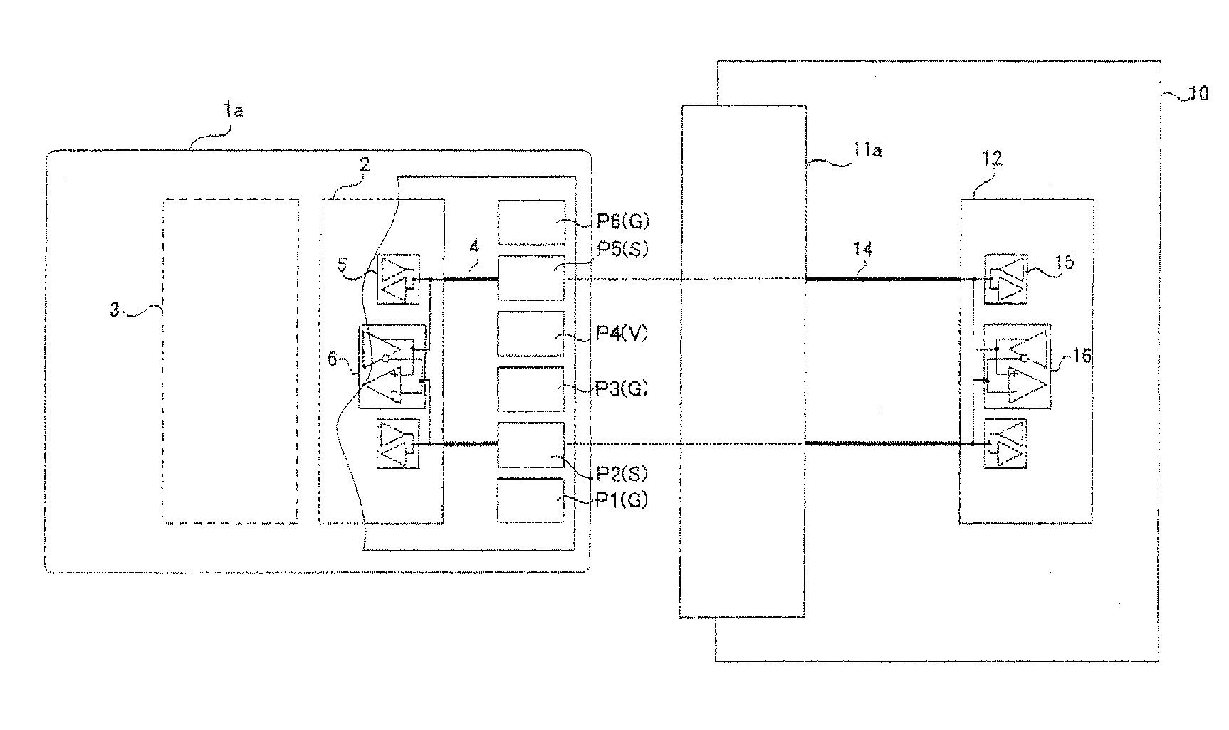
[0043]One of these is to share existing signal pins P(S) of a memory card as illustrated in FIG. 1, between both transmission systems of single-ended transmission and differential transmission (hereinafter referred to as a “pin sharing configuration”). A memory card employing the “pin sharing configuration” is assumed to be a memory card of a reference example 1. According to the “pin sharing configuration”, a controller LSI 2 within the memory card includes a single-ended transmission I / O circuit 5, and a differential transmission I / O circuit 6 (a controller LSI 12 on a host device side has the same configuration). Further, the single-ended I / O circuit 5 and the differential transmission I / O circuit 6 share wiring 4 on a printed-circuit board within a memory card 1a, contact terminals (not depicted) of a memory card socket 11a, wiring 14 on a printed-circuit board within a host device.

[0044]As described above, the differential transmission system allows signal transmission on the o...

reference example 2

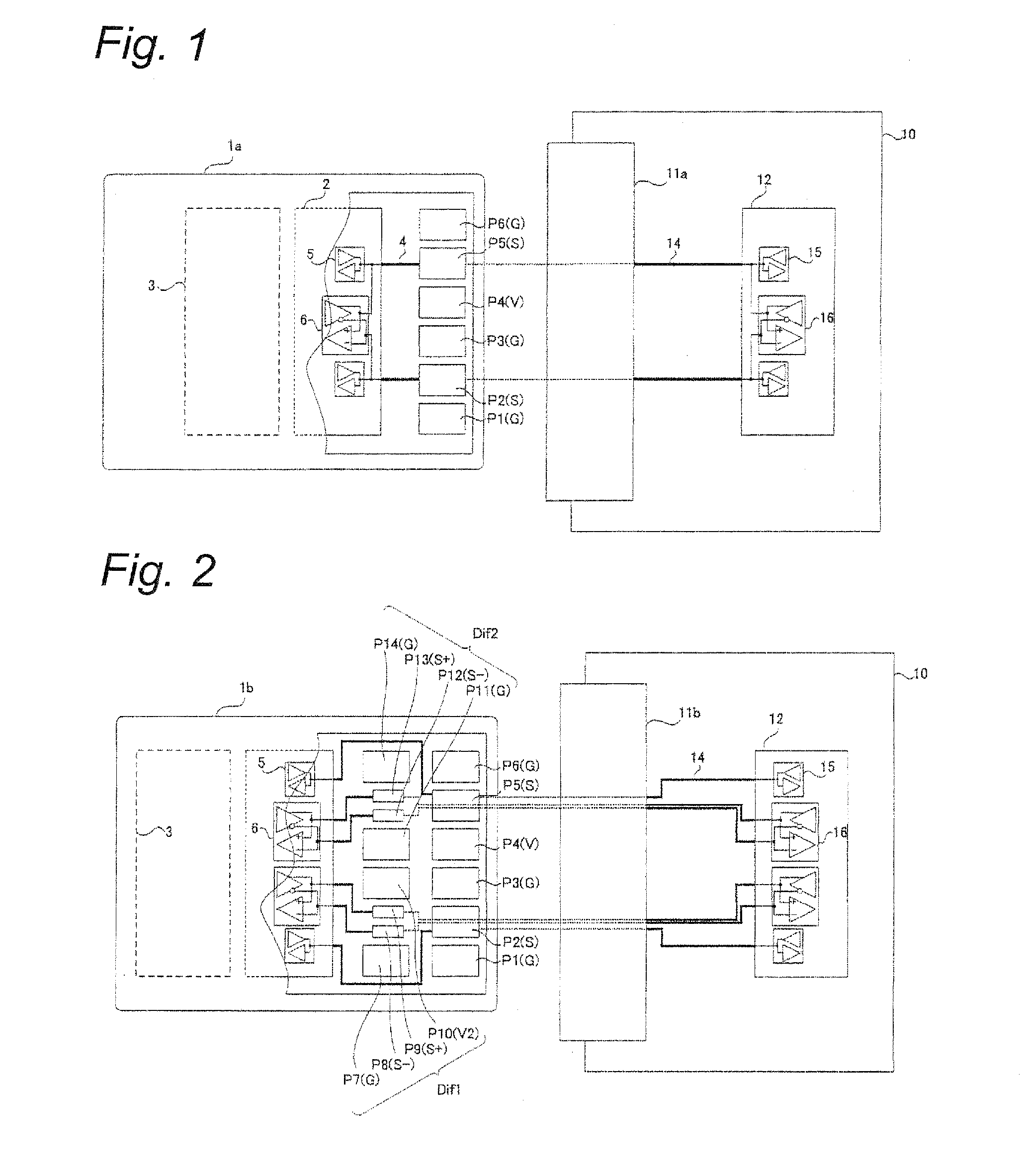
[0045]Another method for realizing the introduction of the differential transmission system to memory cards that have been conducted signal transmission with a host device based on the single-ended transmission system is to additionally provide dedicated pins used exclusively for differential transmission (hereinafter referred to as a “differential pin addition configuration”). A memory card employing the “differential pin addition configuration” is assumed to be a memory card of a reference example 2.

[0046]When additionally providing new differential pins to the memory card 1a illustrated in FIG. 1, for example, an additional pin arrangement as illustrated for a memory card 1b in FIG. 2 is conceivable. Among the newly provided pins of the memory card 1b in FIG. 2 (a second line of pins), differential pins P(S+) and P(S−) are for realizing impedance matching important in the high-speed differential transmission by being provided in a small size, reducing a component in a load capaci...

embodiment 1

[0051]FIG. 4A to FIG. 4E are schematic diagrams illustrating a configuration of a memory card socket 400 according to an embodiment 1. Specifically, FIG. 4A is a top view of the memory card socket 400, and dotted and dashed lines illustrate a transparent view covered under a cover shell 310. Further, FIG. 4B is a rear view of the memory card socket 400. An upper view of FIG. 4C is a cross-sectional view taken along line A3-B3 in FIG. 4A, and a lower view of FIG. 4C is a cross-sectional view taken along line A3′-B3′ in FIG. 4A. FIG. 4D is a schematic diagram when the memory card 1b including the differential transmission pins for high-speed signal transmission, and the stable potential pins of different potentials and adjacently provided on left and right side of the differential pair pins is inserted. An upper view of FIG. 4E is a cross-sectional view taken along line A4-B4 in FIG. 4D, and a lower view of FIG. 4E is a cross-sectional view taken along line A4′-B4′ in FIG. 4D.

[0052]Th...


PUM


Abstract

A high-speed interface connector is used for connecting a cable or a memory card each having a differential transmission system signal pin arrangement including a pair of differential transmission signaling pins that are adjacent to each other and two stable potential pins provided on both sides of the pair of differential transmission signaling pins, the two stable potential pins having potentials different from each other. The connector includes: a first and a second contact terminals for differential transmission respectively connected to the pair of differential transmission signaling pins; and a third and a fourth contact terminals provided on both sides of the first and the second contact terminal, the third contact terminal adjacent to the first contact terminal being connected to one of the two stable potential pins, and the fourth contact terminal adjacent to the second contact terminal having a potential identical to that of the third contact terminal.

Description

BACKGROUND[0001]1. Technical Field[0002]This application is based on and claims the benefit of priority from Japanese Patent Application No. 2011-28303, filed in Japan on Feb. 14, 2011, the content of which is incorporated herein by reference.[0003]The present invention relates to high-speed interface connectors for connecting a differential transmission system signal pin arrangement. In particular, the present invention relates to such as a memory card socket for insertably connecting a memory card having a differential transmission system signal pin arrangement, and a USB cable connector for connecting a USB cable.[0004]2. Background Art[0005]In these days, memory cards are widely used as storage media for storing pictures and movies that are taken by such as digital still camera and a digital video camera, as well as storage media for mobile phones for storing various contents including pictures and movies. In addition, memory cards are also used as bridge media when various cont...

Claims


Application Information

Patent Timeline
Patent Type & Authority Patents(United States)
IPC IPC(8): H01R24/00
CPCH01R13/6461H01R12/712
Inventor SUENAGA, HIROSHINAKAMURA, YUTAKAFUKUMOTO, YUKIHIRO
Owner PANASONIC CORP
Why Eureka
Try Eureka