Bearing device for wheel
a bearing device and wheel technology, applied in the direction of bearing unit rigid support, coupling, transportation and packaging, etc., can solve the problems of spline fitting, cost increase, tooth surface damage, etc., and achieve high coupling strength, high reliability, and easy and accurate confirmation of the accuracy of the re-formed recess-projection fitting structure.
- Summary
- Abstract
- Description
- Claims
- Application Information
AI Technical Summary
Benefits of technology
Problems solved by technology
Method used
Image
Examples
first embodiment
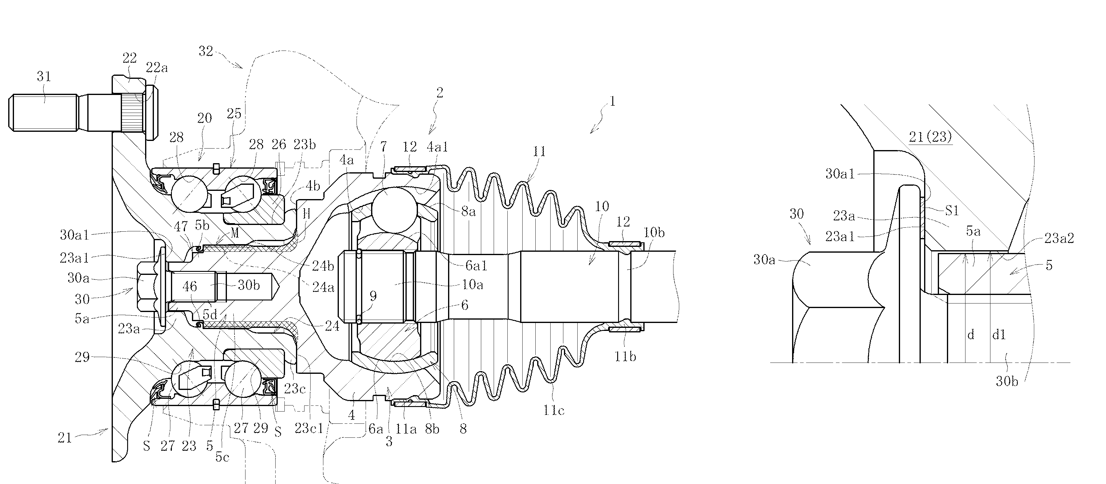
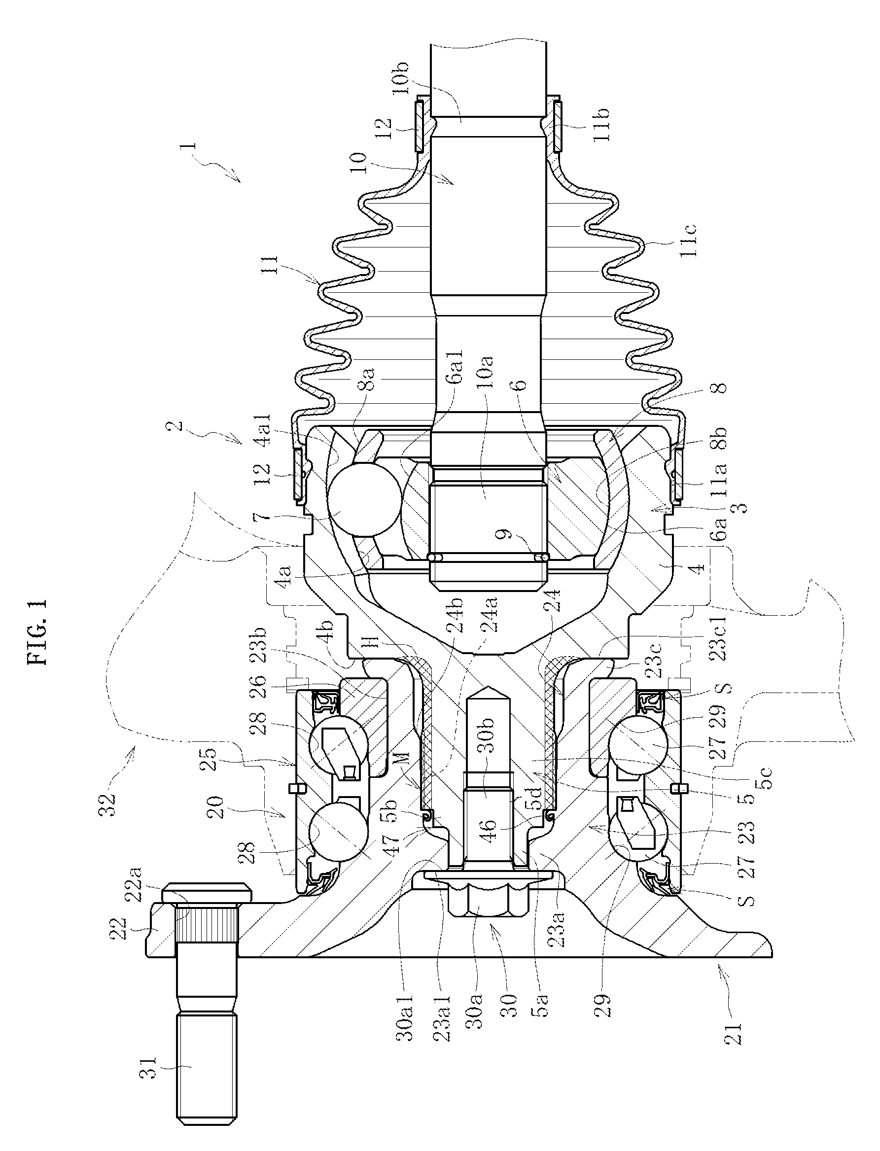
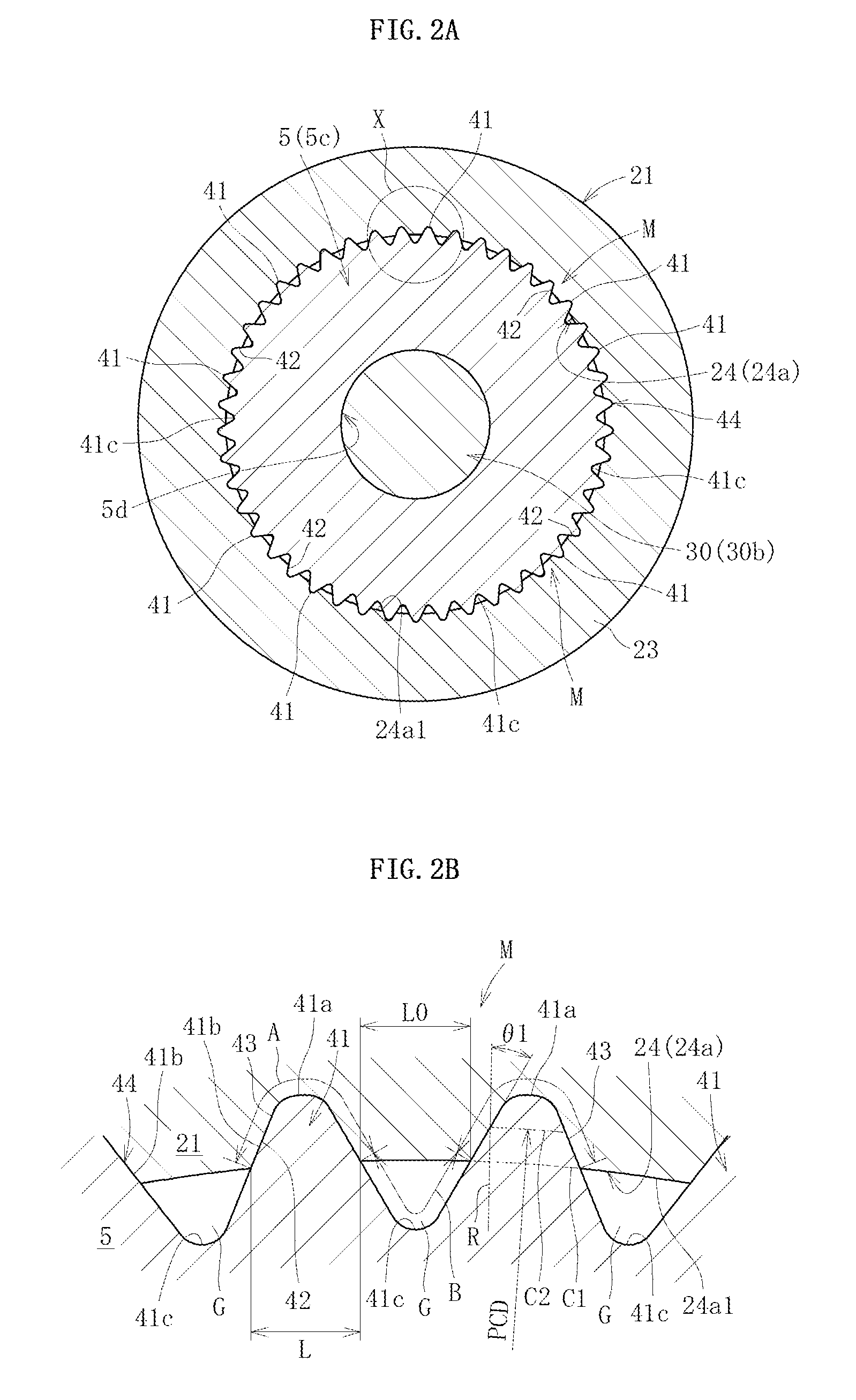
[0082]FIG. 1 is a sectional view of a bearing device for wheel 1 according to the first invention of the present application. A main part of the bearing device for wheel 1 illustrated in FIG. 1 is formed of an integral piece of a double row bearing for wheel 20, which comprises a hub wheel 21, and a constant velocity universal joint 2. Note that, in the following description, an inboard side and an outboard side respectively refer to sides on an inner side and an outer diameter side in a vehicle width direction of a vehicle under a state in which the bearing device for wheel 1 is mounted to the vehicle. In FIG. 1, the right side corresponds to the inboard side and the left side corresponds to the outboard side.
[0083]A main part of the constant velocity universal joint 2 is formed of an outer joint member 3, an inner joint member 6 arranged on an inner diameter side with respect to the outer joint member 3, a plurality of balls 7 interposed between the outer joint member 3 and the in...
second embodiment
[0136]FIG. 10 is a sectional view of a bearing device for wheel 1 according to the first invention of the present application. The bearing device for wheel 1 illustrated in FIG. 10 is different from the bearing device for wheel 1 illustrated in FIG. 1 mainly in that the end surface 23c1 of the crimped portion 23c of the hub wheel 21 and the back surface 4b of the mouth portion 4 are kept out of contact with each other. In this case, as illustrated also in FIG. 11A on an enlarged scale, a gap 60 is provided between the end surface 23c1 of the crimped portion 23c and the back surface 4b of the mouth portion 4. The gap 60 thus formed more effectively prevents generation of abnormal noise which may be caused by contact of the mouth portion 4 of the outer joint member 3 and the hub wheel 21.
[0137]In this way, when the end surface 23c1 of the hub wheel 21 and the back surface 4b of the mouth portion 4 are kept out of contact with each other, foreign matter intrusion prevention means for t...
third embodiment
[0217]FIG. 28 is a sectional view of a bearing device for wheel according to the second invention of the present application. The bearing device for wheel illustrated in FIG. 28 is different from that illustrated in FIG. 16 mainly in that a step portion 122f is provided at an outboard-side end portion of the cylindrical portion 120 of the hub wheel 101 and that a ring-like receiving member 160 separate from the hub wheel 101 is fitted to the step portion 122f so that the head portion 150a of the bolt member 150 is received by the receiving member 160. Specifically, in this embodiment, an outboard-side end surface 160a of the receiving member 160 serves as a receiving surface F′ for receiving the seat surface 150a1 of the bolt member 150. Other components are substantially the same as those of the bearing device for wheel illustrated in FIG. 16. Thus, the same reference symbols are used to omit redundant description.
[0218]Note that, although not described with reference to the drawin...
PUM
 Abstract
Description
Claims
Application Information
 - R&D
- Intellectual Property
- Life Sciences
- Materials
- Tech Scout
- Unparalleled Data Quality
- Higher Quality Content
- 60% Fewer Hallucinations
Browse by: Latest US Patents, China's latest patents, Technical Efficacy Thesaurus, Application Domain, Technology Topic, Popular Technical Reports.
© 2025 PatSnap. All rights reserved.Legal|Privacy policy|Modern Slavery Act Transparency Statement|Sitemap|About US| Contact US: help@patsnap.com


