
Joint use of multi-carrier and single-carrier multiplexing schemes for wireless communication

a wireless communication and multi-carrier technology, applied in the field of wireless communication joint use of multi-carrier and single-carrier multiplexing schemes, can solve the problems of reducing system capacity, reducing power efficiency, and technology not being well suited to simultaneous delivery of high-speed signals such as broadband data, so as to facilitate data stream transmission, facilitate transmission in ofdm mode, and restrict scheduler operation

Active Publication Date: 2014-04-22
QUALCOMM INC
View PDF38 Cites 6 Cited by
  • Summary
  • Abstract
  • Description
  • Claims
  • Application Information

AI Technical Summary

Benefits of technology

This approach enhances system capacity, reduces interference, and optimizes power usage by leveraging the strengths of both OFDM and SC-FDM, achieving better link efficiency and spectral efficiency while maintaining low PAPR.

Problems solved by technology

However, such channel reuse can decrease capacity of systems besides causing interference at cell / sector boundaries that share the channels.
Hence, while CDMA may effectively deliver many low data rate signals like mobile voice, this technology may not be well suited for simultaneous delivery of high speed signals such as broadband data.
While OFDM systems facilitate servicing several users simultaneously by assigning different sets of orthogonal sub carriers to different users, they suffer from high PAPR (Peak to Average Power Ratio) leading to lower power efficiency.
However, due to various factors SC-FDM can restrict operations which necessitates communication systems / methods that can provide flexibility while optimizing power usage.

Method used


Image

  • Joint use of multi-carrier and single-carrier multiplexing schemes for wireless communication
  • Joint use of multi-carrier and single-carrier multiplexing schemes for wireless communication
  • Joint use of multi-carrier and single-carrier multiplexing schemes for wireless communication

Examples


Embodiment Construction

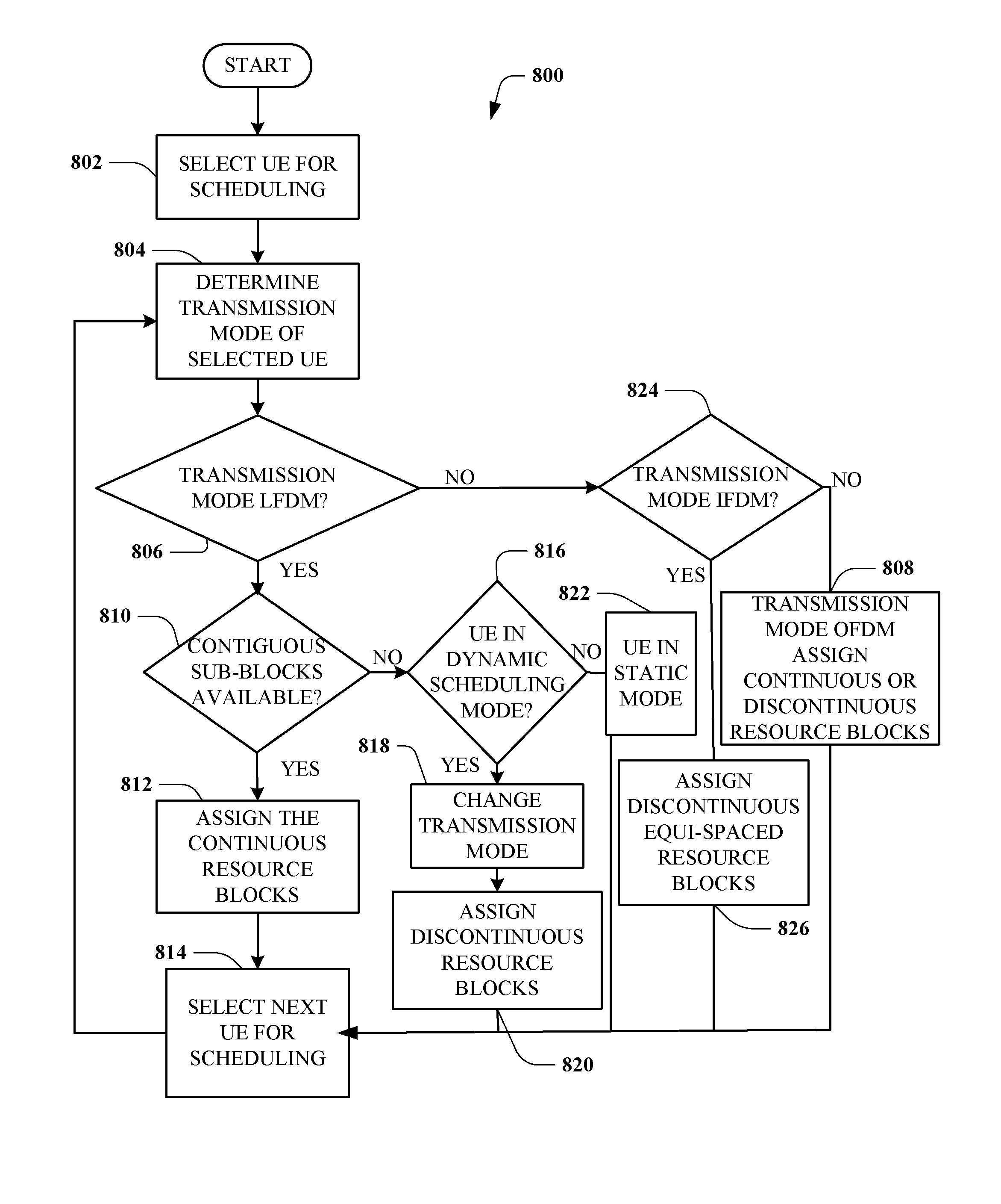
[0032]The claimed subject matter is now described with reference to the drawings, wherein like reference numerals are used to refer to like elements throughout. In the following description, for purposes of explanation, numerous specific details are set forth in order to provide a thorough understanding of the claimed subject matter. It may be evident, however, that the claimed subject matter may be practiced without these specific details. In other instances, well-known structures and devices are shown in block diagram form in order to facilitate describing the claimed subject matter.

[0033]Various embodiments are now described with reference to the drawings, wherein like reference numerals are used to refer to like elements throughout. In the following description, for purposes of explanation, numerous specific details are set forth in order to provide a thorough understanding of one or more aspects. It may be evident however, that such embodiment(s) may be practiced without these ...


PUM


Abstract

A communication system that facilitates transmissions in accordance with a single-carrier (SC) multiplexing scheme, a multi carrier (MC) multiplexing scheme or a combination thereof is disclosed. Based on various factors such as attributes associated with a UE (user equipment) or availability of resources, a base station can signal to the UE an appropriate multiplexing scheme to be adopted for particular transmissions. The UE can be scheduled for transmission in a semi-static mode wherein the UE employs the transmission scheme for a particular time interval or it may change the mode dynamically for different transmissions. For transmissions from the UE comprising a plurality of data streams with dissimilar attributes, the base station implements a MIMO (multiple input multiple output) system for the UE. This facilitates a UE to dynamically switch between or simultaneously adopt the various multiplexing schemes for communications and thereby fully utilize advantages associated with the different schemes.

Description

CROSS-REFERENCE TO RELATED APPLICATIONS[0001]This application claims the benefit of priority under 35 U.S.C. Section 119 from U.S. Provisional Patent Application Ser. No. 60 / 863,885 entitled “JOINT USE OF MULTI-CARRIER AND SINGLE-CARRIER MULTIPLEXING SCHEMES FOR WIRELESS COMMUNICATION”, filed on Nov. 1, 2006, the entirety of which is incorporated hereby by reference.BACKGROUND OF THE INVENTION[0002]Wireless communication systems are widely deployed to provide various types of communications such as voice, data, video, etc. These systems may be multiple-access systems capable of supporting communication with multiple access terminals by sharing available system resources (e.g., bandwidth and transmit power). Examples of such multiple-access systems include code division multiple access (CDMA) systems, time division multiple access (TDMA) systems, frequency division multiple access (FDMA) systems, orthogonal frequency division multiple access (OFDMA) systems or SC-FDM. Typically, a wi...

Claims


Application Information

Patent Timeline
Patent Type & Authority Patents(United States)
IPC IPC(8): H04W4/00H04J11/00
CPCH04L5/0092H04L5/0007H04L1/0003H04L5/0023H04L5/0041H04L1/06H04L1/0025H04L5/0039H04L27/2613H04L5/006H04L27/26134H04L27/26H04W88/02H04L65/00
Inventor XU, HAOMALLADI, DURGA PRASAD
Owner QUALCOMM INC
Learn More