
Diagnostic code generation terminal, diagnostic method and program for diagnostic code generation terminal

a diagnostic code and terminal technology, applied in the field of diagnostic code generation terminals, diagnostic methods and programs, can solve problems such as the inability to receive support while offline, the user may not notice if an operator views and replicates data, and the inability to start diagnostics for recovering from the failure during communication failures

Active Publication Date: 2014-04-15
OPTIM
View PDF10 Cites 0 Cited by
  • Summary
  • Abstract
  • Description
  • Claims
  • Application Information

AI Technical Summary

Benefits of technology

[0011]In addition, when allowed to login from an operator terminal to a user terminal through remote login or the like and operate the user terminal, an operator can freely manipulate data in the user terminal. As a result, a user may not notice if an operator views and replicates the data. Such a user's anxiety may prevent an explosive boom of the remote support system.
[0033]The present invention can provide a diagnostic code generation terminal and a diagnostic method, and a program for a diagnostic code generation terminal, in which a diagnostic result is generated as a diagnostic code, the digit number of this diagnostic code is reduced, and no useless diagnoses are performed, in order to check the setting status of a user terminal.

Problems solved by technology

As a result, a user may not notice if an operator views and replicates the data.
Furthermore, in transferring user's screen information and remote support conducting remote login, users cannot receive support while offline.
A user wishes to receive remote support required for communication, but diagnosis for recovering from the failure may not be able to be started during communication failure.

Method used


Image

  • Diagnostic code generation terminal, diagnostic method and program for diagnostic code generation terminal
  • Diagnostic code generation terminal, diagnostic method and program for diagnostic code generation terminal
  • Diagnostic code generation terminal, diagnostic method and program for diagnostic code generation terminal

Examples


second embodiment

The Second Embodiment

Extraction of Select Object from the Operator Terminal 150

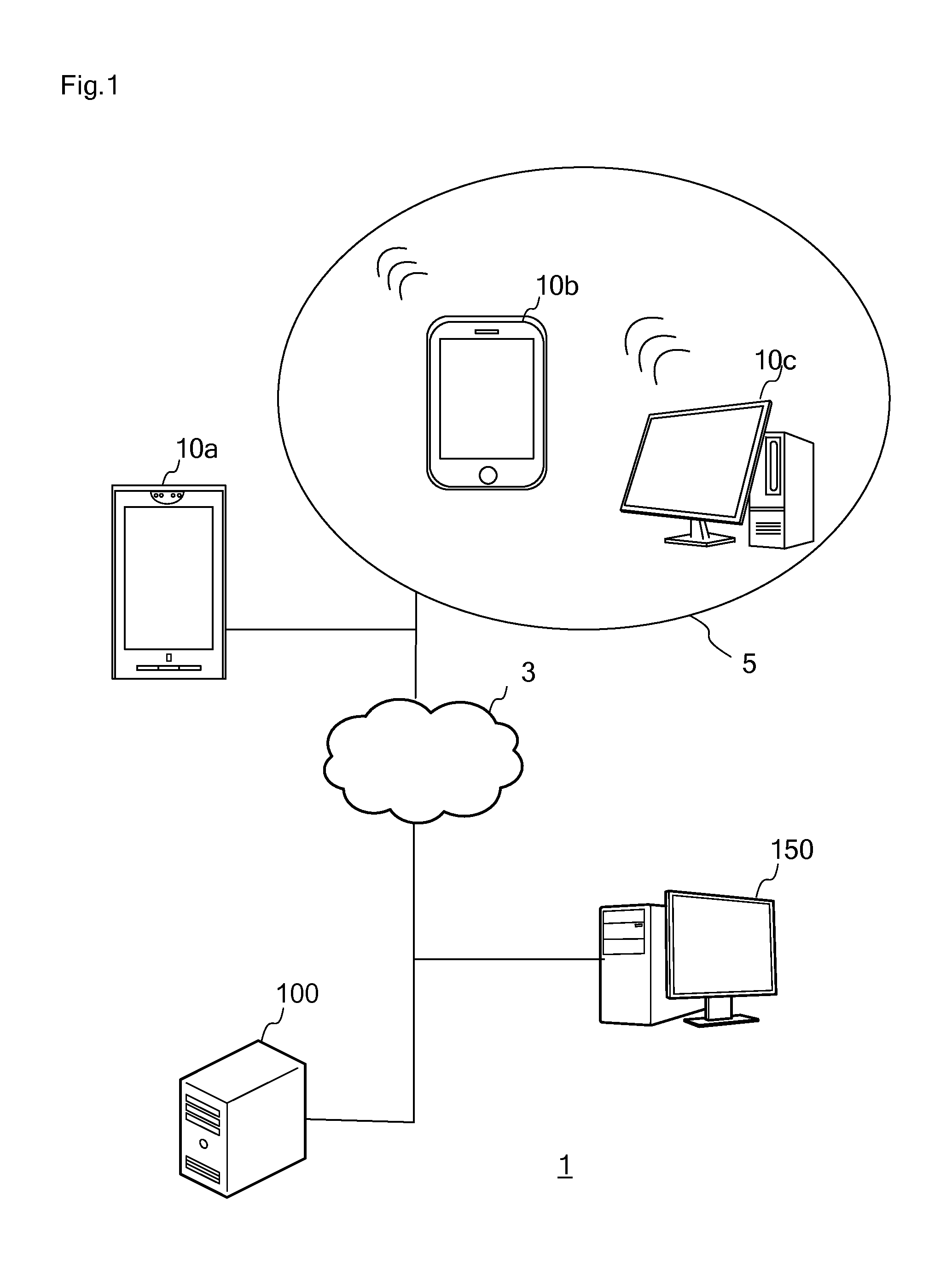
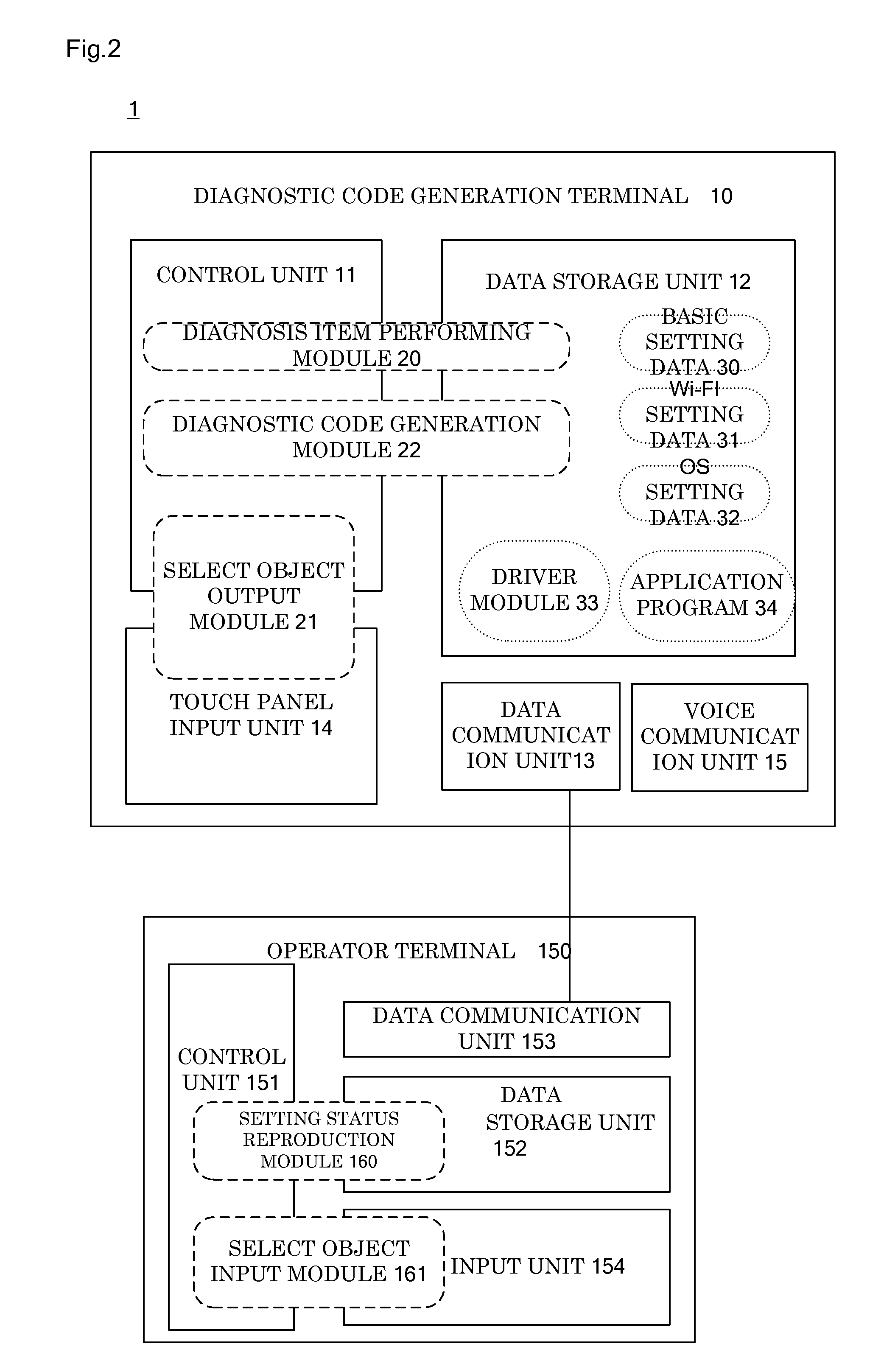
[0122]In the second embodiment to be explained hereinafter, unlike the first embodiment, the diagnostic code generation terminal 10 and the operator terminal 150 are connected for enabling data communication with each other.

[0123]From the steps S70 to S74 of the diagnostic code generation process 2, the processes are the same only except the steps S01 to S05 of the diagnostic code generation process and N is changed to L. Therefore, the explanation is omitted.

[0124]In the step S75, the diagnostic code generation terminal 10 extracts and outputs an L=1 select object is extracted, but a select object is selected and extracted from the operator terminal 150.

[0125]FIG. 18 shows the screen image of an operator terminal 150 when the present process is executed. At this point, the select object specification window 62 is displayed on the operator terminal 150. The select object specification window 62 is a windo...

third embodiment

The Third Embodiment

Transmission of Diagnostic Code

[0130]In the third embodiment to be explained hereinafter, unlike the first embodiment, the diagnostic code generation terminal 10 and the operator terminal 150 are connected for enabling data communication with each other. The third embodiment executes the same process as the diagnostic code generation process of the first embodiment, only except the basic code output process of the step S04 and the output process of the N-th diagnostic code of the step S11. In the present embodiment, the basic code output process is the basic code transmission process, and the N-th diagnostic code output process is the N-th diagnostic code transmission process.

[0131]Specifically, the diagnostic code generation terminal 10 transmits a basic diagnostic code to the operator terminal 150. The operator terminal 150 that has received a basic diagnostic code executes the setting status reproduction process. “DIAGNOSTIC CODE IS INPUT?” in the step S30 of ...


PUM


Abstract

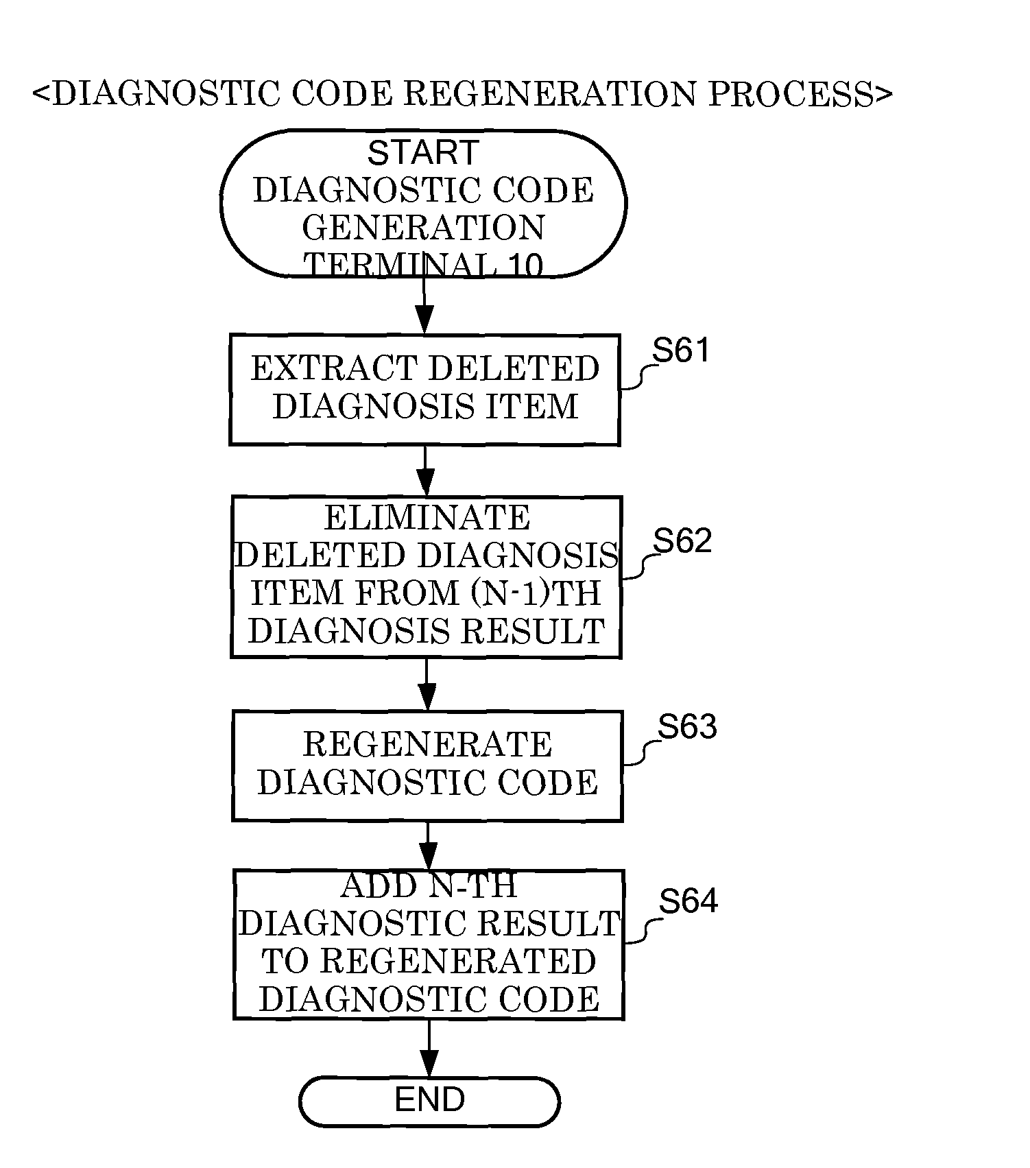
The diagnostic method is provided with no leakage of user's private information, less errors in reproduction of the setting status, and no performing of useless diagnoses. Input from a user is received by outputting a select object for limiting a diagnosis item of the diagnostic code generation terminal 10 to the diagnostic code generation terminal 10, a diagnosis item corresponding to the select object is determined in accordance with the input from the user, and performing diagnosis of the determined diagnosis item is performed. Then, a diagnostic code reflecting the result of the performed diagnosis is generated, and the setting status of the diagnostic code generation terminal 10 is reproduced by inputting the diagnostic code from an operator terminal 150. Even when a diagnostic code is repeatedly generated, information on the past diagnostic code is included in the next diagnostic code, and thus useless diagnosis processes are reduced.

Description

[0001]This application is based on and claims the benefit of priority from Japanese Patent Application No. 2011-208246, filed on 23 Sep. 2011, the content and teachings of which are incorporated herein by reference.TECHNICAL FIELD[0002]The present invention relates to a diagnostic code generation terminal, a diagnostic method, and a program for the diagnostic code generation terminal that utilize a diagnostic code used for remotely supporting a smart phone, a personal computer, and the like.BACKGROUND ART[0003]In recent years, various services have been provided for users by connecting portable terminals with a web server and the like through a public line network. In particular, advanced services, which have been provided for personal computers conventionally, has become possible to provide for mobile phones by the appearance of smart phones (highly functional mobile phones).[0004]In order to maximize the use of such advanced web services and the high functionality of smart phones,...

Claims


Application Information

Patent Timeline
Patent Type & Authority Patents(United States)
IPC IPC(8): G06F11/00
CPCG06F11/079
Inventor SUGAYA, SHUNJI
Owner OPTIM
Learn More