
Hermetically sealed disk drive with fill port valve

a technology of fill port valve and disk drive, which is applied in the direction of recording carrier contruction details, electrical apparatus contruction details, instruments, etc., can solve the problems of non-negligible amount of gas leakage, affecting the head performance, and rotating the mounted disks

Active Publication Date: 2014-04-15
WESTERN DIGITAL TECH INC
View PDF10 Cites 60 Cited by
  • Summary
  • Abstract
  • Description
  • Claims
  • Application Information

AI Technical Summary

Benefits of technology

The patent text describes a problem with conventional hard disk drives that contain a gas other than air. Gas leakage can affect the performance and reliability of the drive, and it can be difficult to re-fill the enclosure with the gas after a leak. The patent proposes an improved structure and method for re-filling the enclosure with the gas and then re-sealing it. This would allow for easier maintenance and replacement of the gas without the need for a small ball component.

Problems solved by technology

Rotation of the spindle motor hub results in rotation of the mounted disks.
However, air bearing sliders have been designed for use in disk drive enclosures that contain helium, because an inert gas may not degrade lubricants and protective carbon films as quickly as does oxygen.
Although some negligible amount of gas leakage may be unavoidable, a non-negligible amount of gas leakage is undesirable because it can alter the thickness of the gas lubrication film between the head and the disk, and thereby affect the performance of the head.
A non-negligible amount of gas leakage is also undesirable because it can alter the tribochemistry of the head disk interface, possibly leading to degradation in reliability, head crashes, and associated data loss.
However, if the disk drive loses the gas due to a leak, and the leak is repaired, the disk drive may need to be refilled with the gas.
This can present a problem if the fill port cannot be conveniently or practically reopened and / or resealed.
The interference fit between the ball and the hole can seal the gas within the disk drive.
Either option would typically undesirably require the disk drive cover to be removed and replaced, and would require manufacturing personnel to keep track of the loose and relatively small ball component.

Method used


Image

  • Hermetically sealed disk drive with fill port valve
  • Hermetically sealed disk drive with fill port valve
  • Hermetically sealed disk drive with fill port valve

Examples


Embodiment Construction

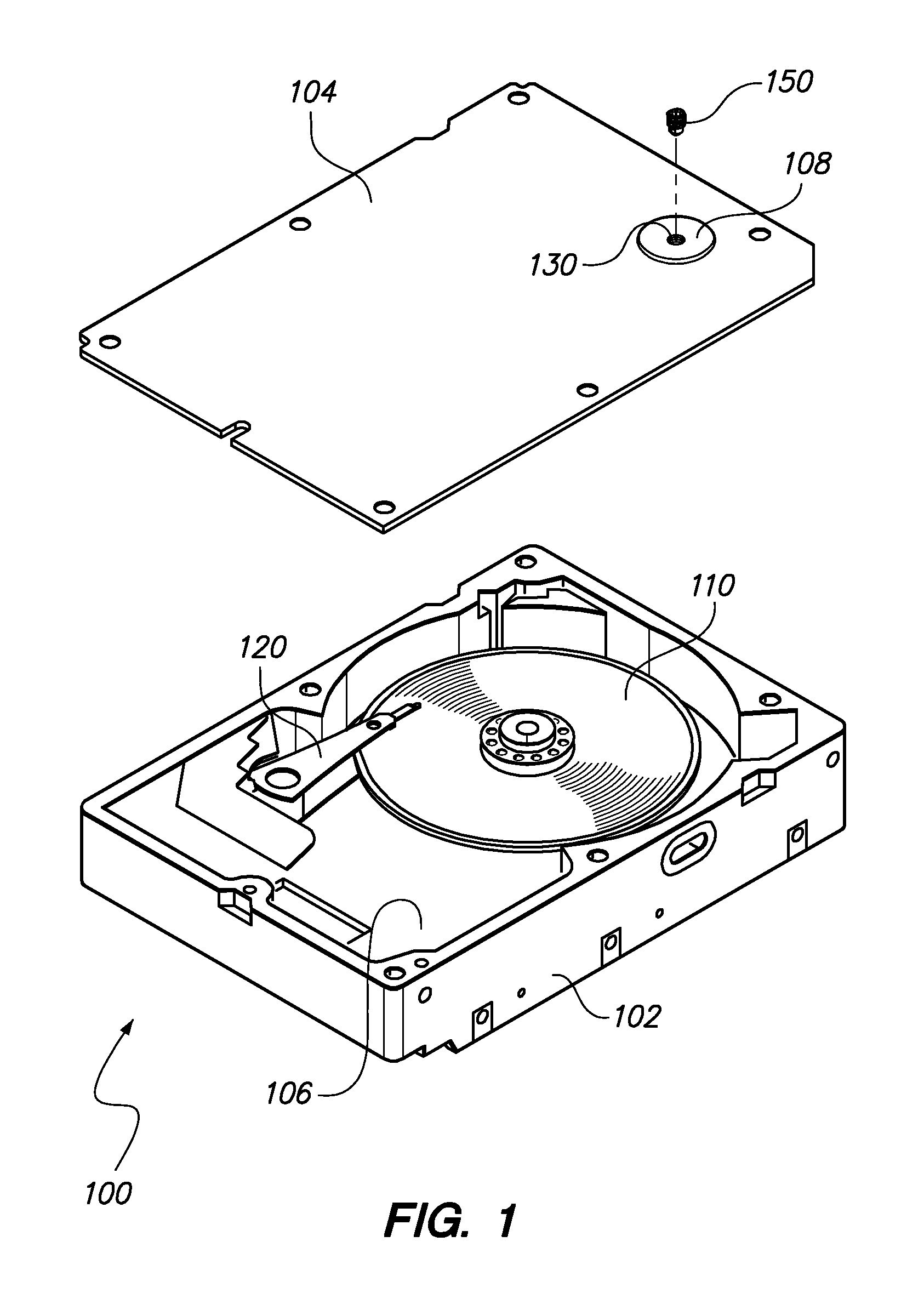
[0020]FIG. 1 is a perspective exploded view of a disk drive 100 according to an embodiment of the present invention. The disk drive 100 includes a disk drive base 102, and a disk drive cover 104, that together form a disk drive enclosure 106. At least one disk 110 is rotatably mounted to the disk drive base 102, within the disk drive enclosure 106. The disk drive 100 also includes a head actuator 120 for positioning a head at desired positions over the major surface of the disk 110.

[0021]Although in the view of FIG. 1 the disk drive cover 104 is exploded away from the disk drive base 102 to show some internal components of the disk drive 100, in the assembled disk drive 100 the disk drive cover 104 is preferably sealed to the disk drive base 102, continuously around its periphery. In this context, being sealed continuously around its periphery implies that a sealant layer (e.g. adhesive, solder, a polymer gasket material) continuously encircles the interior of the disk drive enclosu...


PUM

PropertyMeasurementUnit
thicknessaaaaaaaaaa
pressureaaaaaaaaaa
partial pressureaaaaaaaaaa

Abstract

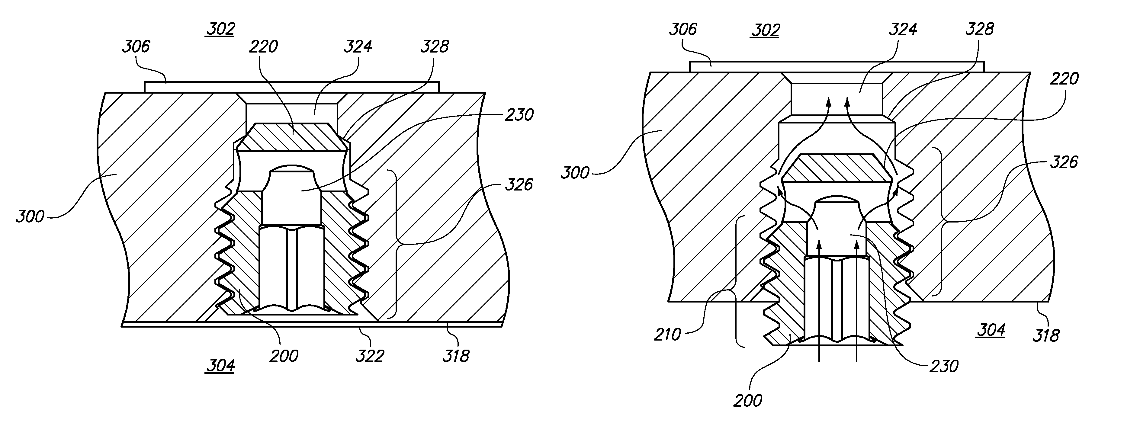
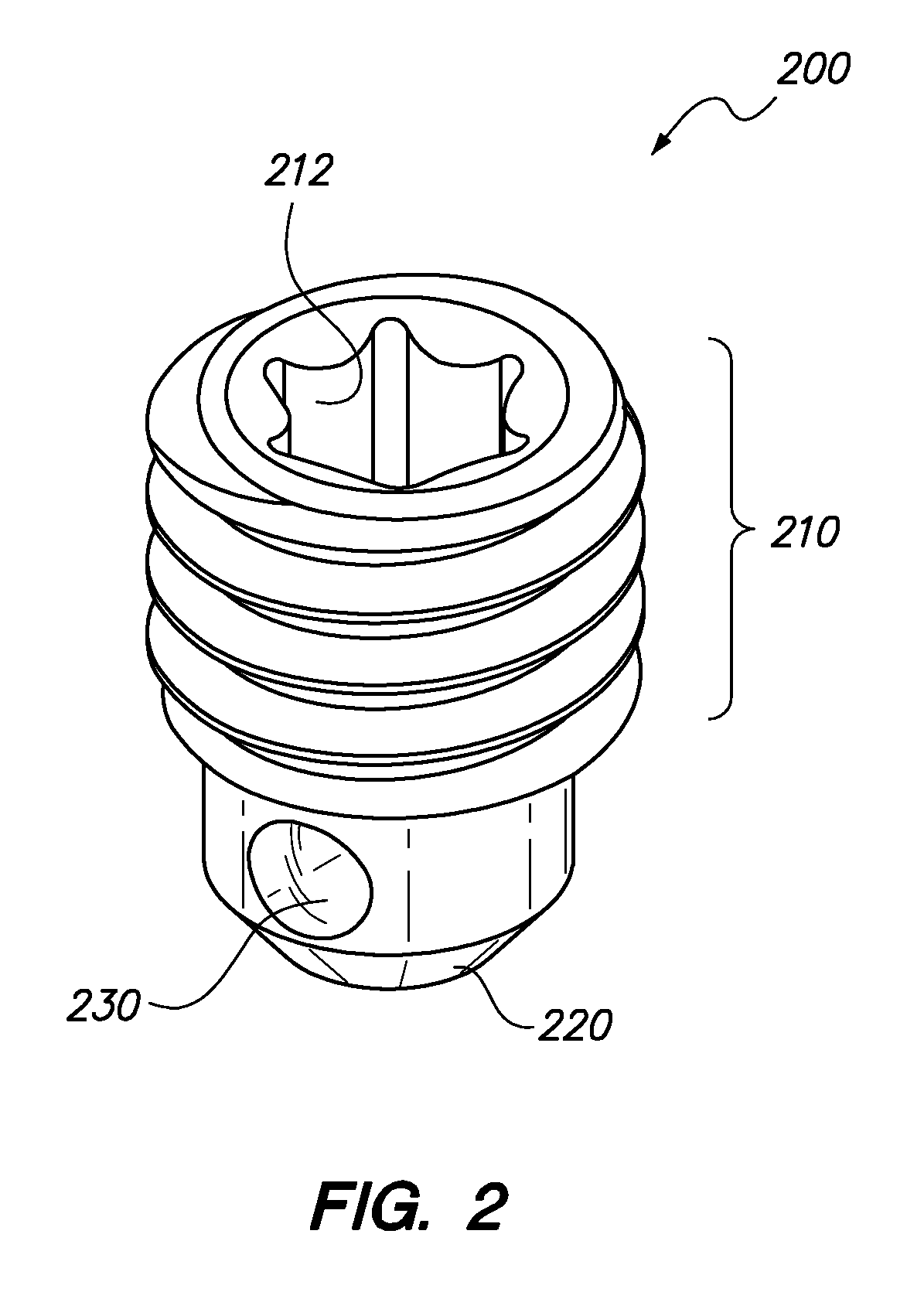
A novel disk drive includes an enclosure and a disk rotatably mounted to and within the enclosure. The disk drive enclosure has a fill port opening with an internally threaded section and an internal annular seating surface. A fill port valve is disposed within the fill port opening. The fill port valve includes an externally threaded section that is engaged with the internally threaded section of the fill port opening, an external annular seating surface in contact with and forming a continuous annular seal with the internal annular seating surface of the fill port opening, and a gas flow channel spanning the externally threaded section of the fill port valve. The disk drive may be helium-filled, and may also include a metal foil seal that is externally adhered to the disk drive enclosure and covers the fill port opening and the fill port valve.

Description

BACKGROUND[0001]The typical hard disk drive includes a head disk assembly (HDA) and a printed circuit board assembly (PCBA) attached to a disk drive base of the HDA. The HDA includes at least one disk (such as a magnetic disk, magneto-optical disk, or optical disk), a spindle motor for rotating the disk, and a head stack assembly (HSA). The PCBA includes electronics and firmware for controlling the rotation of the spindle motor and for controlling the position of the HSA, and for providing a data transfer channel between the disk drive and its host.[0002]The spindle motor typically includes a rotor including one or more rotor magnets and a rotating hub on which disks are mounted and clamped, and a stator. If more than one disk is mounted on the hub, the disks are typically separated by spacer rings that are mounted on the hub between the disks. Various coils of the stator are selectively energized to form an electromagnetic field that pulls / pushes on the rotor magnet(s), thereby rot...

Claims


Application Information

Patent Timeline
Patent Type & Authority Patents(United States)
IPC IPC(8): G11B33/14
CPCG11B33/1466G11B25/043G11B33/1486G11B33/14
Inventor GOLGOLAB, ARMAN V.JACOBY, JON E.
Owner WESTERN DIGITAL TECH INC
Learn More