System for post-treating and transferring preforms

a preform and post-treatment technology, applied in the field of post-treatment preforms, can solve the problems of large temperature differences, high complication and expenditure, and inability to achieve the effect of reducing the number of preforms, and reducing the quality of the preform

Active Publication Date: 2014-04-15
MHT MOLD & HOTRUNNER TECH
View PDF3 Cites 3 Cited by
  • Summary
  • Abstract
  • Description
  • Claims
  • Application Information

AI Technical Summary

Benefits of technology

[0006]As the preform must remain in the receiving cavity for a comparatively long time for cooling so that generally the next preform can already be removed from the injection moulding tool before the preform has cooled down in the receiving cavity to such an extent that it can be removed without the risk of damage it is already usual to employ receiving plates which have a plurality of groups of receiving cavities, wherein each group has as many receiving cavities as the injection moulding tool provides preforms per injection cycle. The individual receiving cavity groups are then successively equipped with preforms so that the individual preform can remain in the receiving cavity for longer than an injection moulding cycle.
[0007]To further reduce the post-treatment time in the removal plate, it has already been proposed in U.S. Pat. No 6,475,422 that a pin be introduced into the preform, by way of the tip of which cooling fluid is passed into the bottom region of the preform. In that case the cooling fluid issues at the tip of the pin and then flows through the annular gap formed between the cooling pin and the inside wall of the preform, and out of the preform into the environment. The preform is thus cooled not only from the exterior but also from the interior.

Problems solved by technology

In the production of the corresponding injection moulding moulds, a high level of complication and expenditure is necessary as the injection moulding mould on the one hand has to be designed for very high pressures and on the other hand it must also have suitable heated and / or cooled passages.
To provide sufficient cooling fluid it is necessary to act on the cooling pin with compressed air, which involves the costly provision of suitable air feed lines and suitable compressors.
In addition that kind of cooling fluid feed leads to very rapid cooling of the bottom portion of the preform while the wall portions and in particular the neck portions are only relatively slowly cooled down, which leads to large temperature differences within the preform, whereby the quality of the preform can be impaired.
Porous post-treatment pins however are relatively complicated and expensive to manufacture and have to be supplied with high pressure to ensure an adequate coolant fluid flow.

Method used


Image

  • System for post-treating and transferring preforms
  • System for post-treating and transferring preforms
  • System for post-treating and transferring preforms

Examples


Embodiment Construction

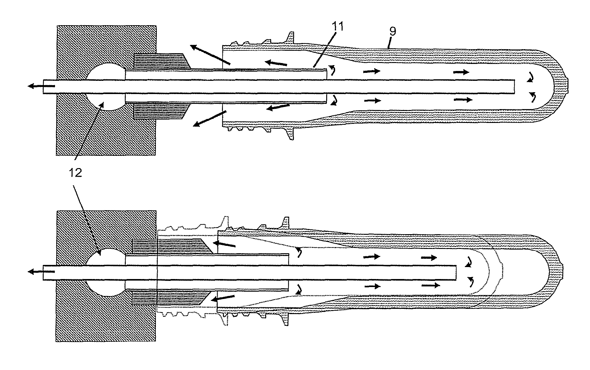
[0037]Based on the described state of the art therefore the object of the present invention is to provide a system for the pre-treatment of preforms produced by injection moulding, which can be operated inexpensively without the provision of compressed air and minimises the temperature gradient within the preform, which inevitably occurs during the post-treatment.

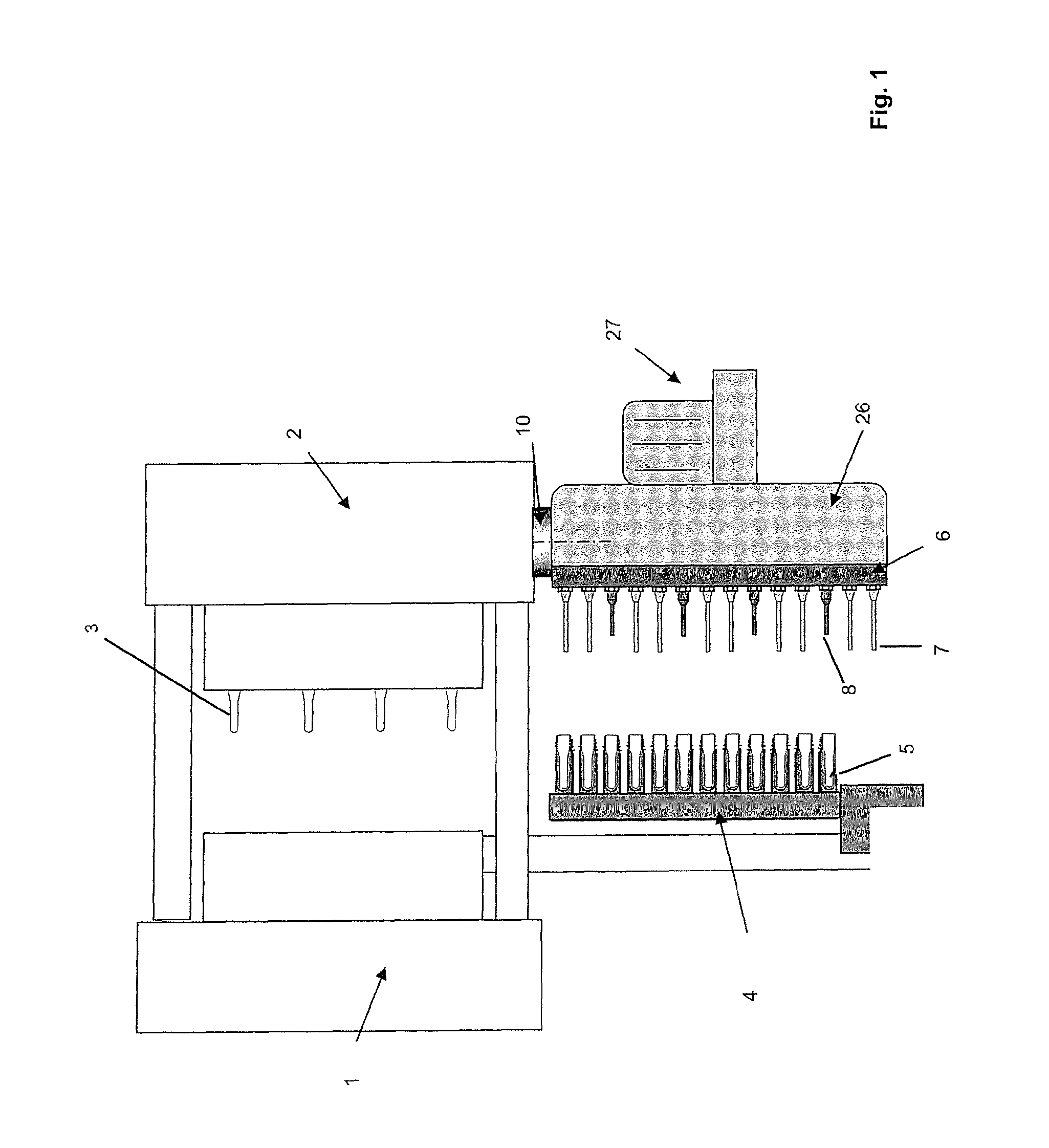
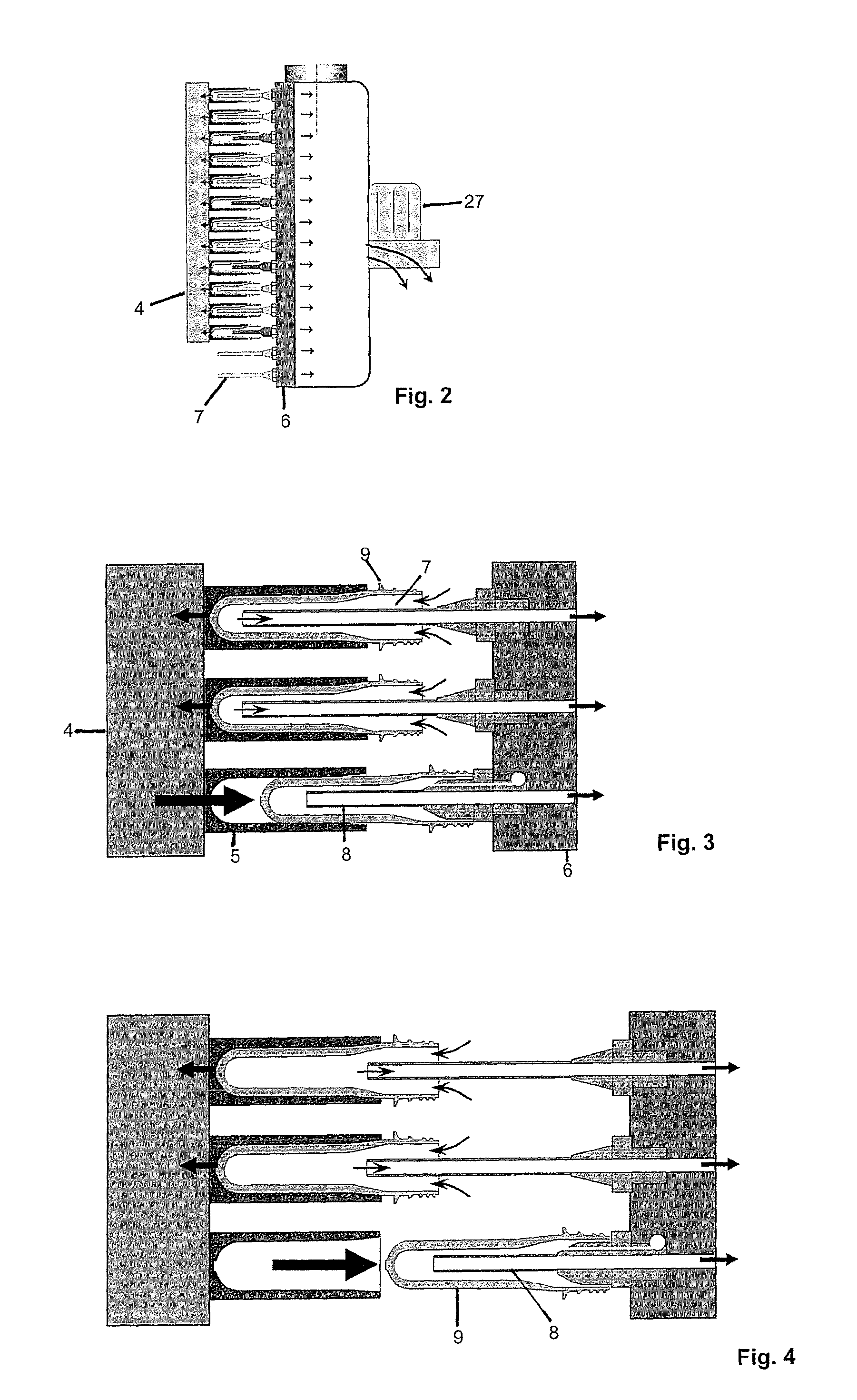
[0038]According to the invention that object is attained by a corresponding system comprising a removal element having at least one receiving element for receiving a preform, and a device for moving the removal element between two tool halves of an opened injection moulding mould and for moving the removal element out of the opened injection moulding mould, a post-treatment element having at least one post-treatment pin having a pin-shaped passage element, of which one end can be connected to the environment or a vacuum or reduced-pressure source and of which the other end has an outlet for a coolant, and a motion device wi...


PUM

PropertyMeasurementUnit
pressureaaaaaaaaaa
pressureaaaaaaaaaa
pressureaaaaaaaaaa

Abstract

A system for the post-treatment of preforms (9) produced by means of injection moulding, including a removal element (4) having at least one receiving element (5) for receiving a preform (9), and a device for moving the removal element (4) between two tool halves of an opened injection moulding mould and for moving the removal element (4) out of the opened injection moulding mould, a post-treatment element (6) having at least one post-treatment pin (7) having a pin-shaped passage element (7), of which one end can be connected to the environment or a vacuum or reduced-pressure source and of which the other end has an outlet (18) for a coolant, and a motion device with which the removal element (4) can be reciprocated relative to the post-treatment element (6) between a first position in which the post-treatment pin (7) is positioned within the receiving element (5) and a second position in which the post-treatment pin (7) is not positioned within the receiving element (5), wherein the removal element (4) and the post-treatment element (6) are so designed that in the first position coolant can be introduced by way of the coolant inlet into a preform held in the receiving element (5) in such a way that it can flow between the inside wall of the preform (9) and the outside wall of the pin-shaped passage element (7) to the coolant outlet (18) and can be discharged by way of the passage element (7).

Description

BACKGOUND OF THE INVENTION[0001]The present invention concerns a system for post-treatment of preforms produced by means of injection moulding.[0002]By way of example commercially available PET bottles are generally produced by stretch blow moulding of the hollow body preform. In that case the hollow body preform is produced in a first step by injection moulding. The stretch blow moulding operation which follows the injection moulding operation can be effected either immediately after production of the hollow body preform or at a later time. In the production of the corresponding injection moulding moulds, a high level of complication and expenditure is necessary as the injection moulding mould on the one hand has to be designed for very high pressures and on the other hand it must also have suitable heated and / or cooled passages.[0003]Usually an injection moulding tool for the production of PET preforms comprises a large number of, for example 96, cavities into which tool cores of ...

Claims


Application Information

Patent Timeline
Patent Type & Authority Patents(United States)
IPC IPC(8): B29B11/08
CPCB29C2045/7214B29C49/6427B29C45/7207B29C49/06B29C2949/0715B29C49/643
Inventor NETER, WITOLDTHOEMMES, HELMUTPETRY, RAINERWAGNER, CHRISTIAN
Owner MHT MOLD & HOTRUNNER TECH
Why Eureka
Try Eureka