
Composite sabot

a composite material and sabot technology, applied in the field of military sabots, can solve the problems of low torsional load capability, failure of composite materials in rifled gun systems, and heavy weight when compared to modern composite materials, and achieve the effect of maximizing the ratio of composite to aluminum and minimizing weigh

Inactive Publication Date: 2014-04-15
UNITED STATES OF AMERICA THE AS REPRESENTED BY THE SEC OF THE ARMY
View PDF10 Cites 6 Cited by
  • Summary
  • Abstract
  • Description
  • Claims
  • Application Information

AI Technical Summary

Benefits of technology

The present invention is a lightweight, metal reinforced, composite sabot projectile that can be used with a variety of caliber rifled gun systems. The sabot is made of a thin layer of aluminum or other metal wedges sandwiched between thin layers of composite material. The composite material is reinforced with metal wedges to provide the necessary torsional strength to withstand firing from a rifled gun tube without any loss of body integrity. The metal surface on the sabot also helps protect the composite material from physical forces and reduces spin, reducing hoop stresses on the sabot. The sabot is made of at least three segments manufactured of composite material, sandwiched between reinforcing metal wedges. The ratio of composite to aluminum should be maximized to minimize weight and maximize range and penetration of the penetrator on target.

Problems solved by technology

While aluminum is a relatively light weight metal, it is certainly heavy when compared to modern composite materials.
However, while composite sabot structures have successfully been used in 120 MM smooth bore gun systems, where there is no spin, i.e. no significant torsional loads; the use of such composite materials in rifled gun systems has failed—composite sabot structures provide only a very low torsional load capability of about the order of 7000 inch-pounds and the spin effect from being fired from a rifled gun causes loss of the sabots body integrity (i.e. the sabots composite structure literally comes apart).
To strengthen sabots for use in rifled gun systems, past attempts to introduce metal supports in the molding process have failed due to incompatibility of coefficient of expansion and contraction of the dissimilar composites and metal materials.
Further, the obturator of a composite sabot is subjected to significant friction, heat and pressure forces during firing from a rifled barrel—such that there is a significant risk of material failure.

Method used


Image

  • Composite sabot
  • Composite sabot
  • Composite sabot

Examples


Embodiment Construction

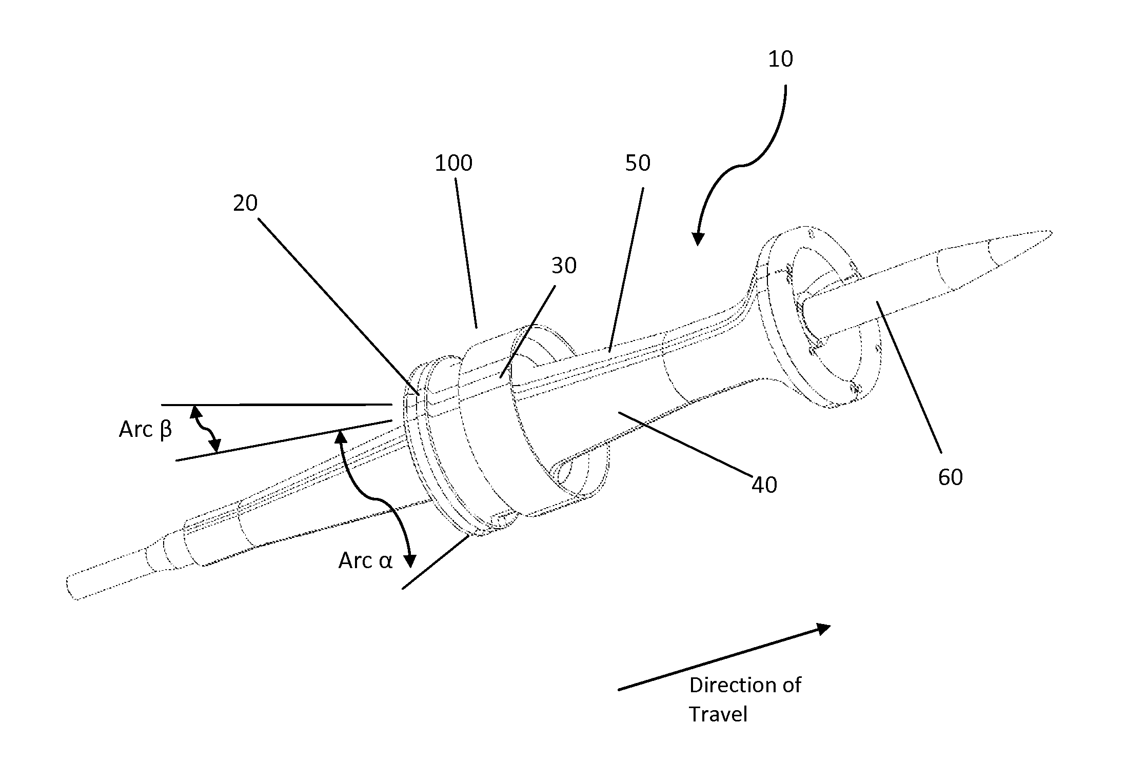
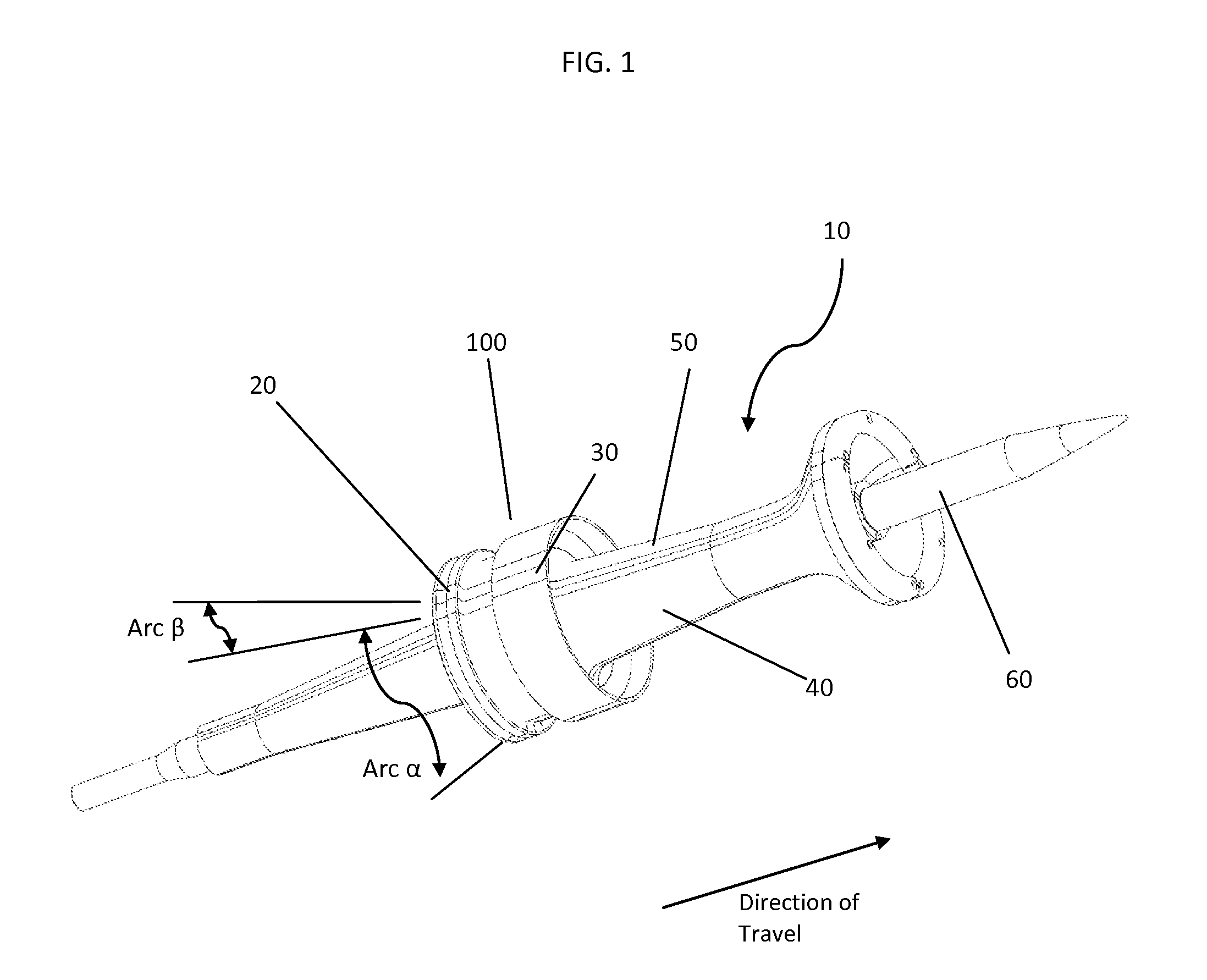
[0017]The present invention comprises a lightweight metal insert reinforced composite sabot projectile for use with large caliber, such as 105 mm or 120 mm rifled gun systems, as well as, medium and small caliber rifled gun systems. Referring to FIG. 1, a sabot of the present invention, 10, wherein, aluminum wedges or plates 20, 30, are inserted longitudinally along the longitudinal axis of the sabot, one aluminum wedge being bonded to each side of each lightweight composite material sabot segment 40, 50 (i.e. sandwiching the composite material segment); each wedge 20, 30, having an identical outline as the composite material sabot segment 40, 50, to which each is affixed; thereby, providing a reinforced composite sabot having the torsional strength required to survive being launched from a rifled gun tube without any loss of its body integrity. The subject sandwiched composite material sabot segments are aligned and held together by mechanical means to form the completed sabot, whi...


PUM

PropertyMeasurementUnit
circumferenceaaaaaaaaaa
torsion forcesaaaaaaaaaa
physical forcesaaaaaaaaaa

Abstract

A lightweight composite sabot useful in large, medium and small caliber rifled gun systems, wherein each of the sabot segments are reinforced with thin aluminum, or other, metal wedges to increase the torsional strength of the sabot body to survive the torsional forces created when fired from a rifled gun tube. And, which composite sabot also has a metal bulkhead about the periphery thereof, to reduce the spin and resulting hoop stresses, and to help protect the composite material during firing.

Description

CROSS-REFERENCE TO RELATED APPLICATIONS[0001]This application claims the benefit under 35 USC §119(e) of U.S. Provisional Patent Application No. 61 / 491,959, filed on Jun. 1, 2011, which provisional application is hereby incorporated herein in its entirety.FEDERAL RESEARCH STATEMENT[0002]The invention described herein may be manufactured, used, and / or licensed by the U.S. Government for U.S. Government purposes, without the payment of any royalty therefore.FIELD OF THE INVENTION[0003]The present invention relates to military sabots, and particularly to such devices with light weight construction, to provide increased velocity and kinetic energy upon impact, and enhanced hoop strength both along the length of the sabot and about the obturator band, to survive launch from rifled gun tube systems.BACKGROUND OF THE INVENTION[0004]High density, long rod penetrators in the form of flechettes, pointed projectiles with vaned tails for stable flight, are utilized as anti-amour weapons, i.e. k...

Claims


Application Information

Patent Timeline
Patent Type & Authority Patents(United States)
IPC IPC(8): F42B14/06
CPCF42B14/061F42B14/06F42B14/062F42B14/068
Inventor MUSALI, SAIFHARHARA, MUNASIRPAYNE, NICHOLASJOINSON, ROGERMUDALIAR, VELANPRILLAMAN, DANIELSINGH, SHRI
Owner UNITED STATES OF AMERICA THE AS REPRESENTED BY THE SEC OF THE ARMY
Learn More