
System and method for generating enhanced density distribution in a three dimensional model of a structure for use in skeletal assessment using a limited number of two-dimensional views

a three-dimensional model and enhanced density technology, applied in the field of skeletal assessment, can solve the problems of outweighing the patient's, failing and unable to provide important 3-d information about the volumetric density and spatial geometry of imaged skeletal structures. , to achieve the effect of reducing patient exposure, equipment cost and examination tim

Active Publication Date: 2014-04-08
HOLOGIC INC
View PDF19 Cites 12 Cited by
  • Summary
  • Abstract
  • Description
  • Claims
  • Application Information

AI Technical Summary

Benefits of technology

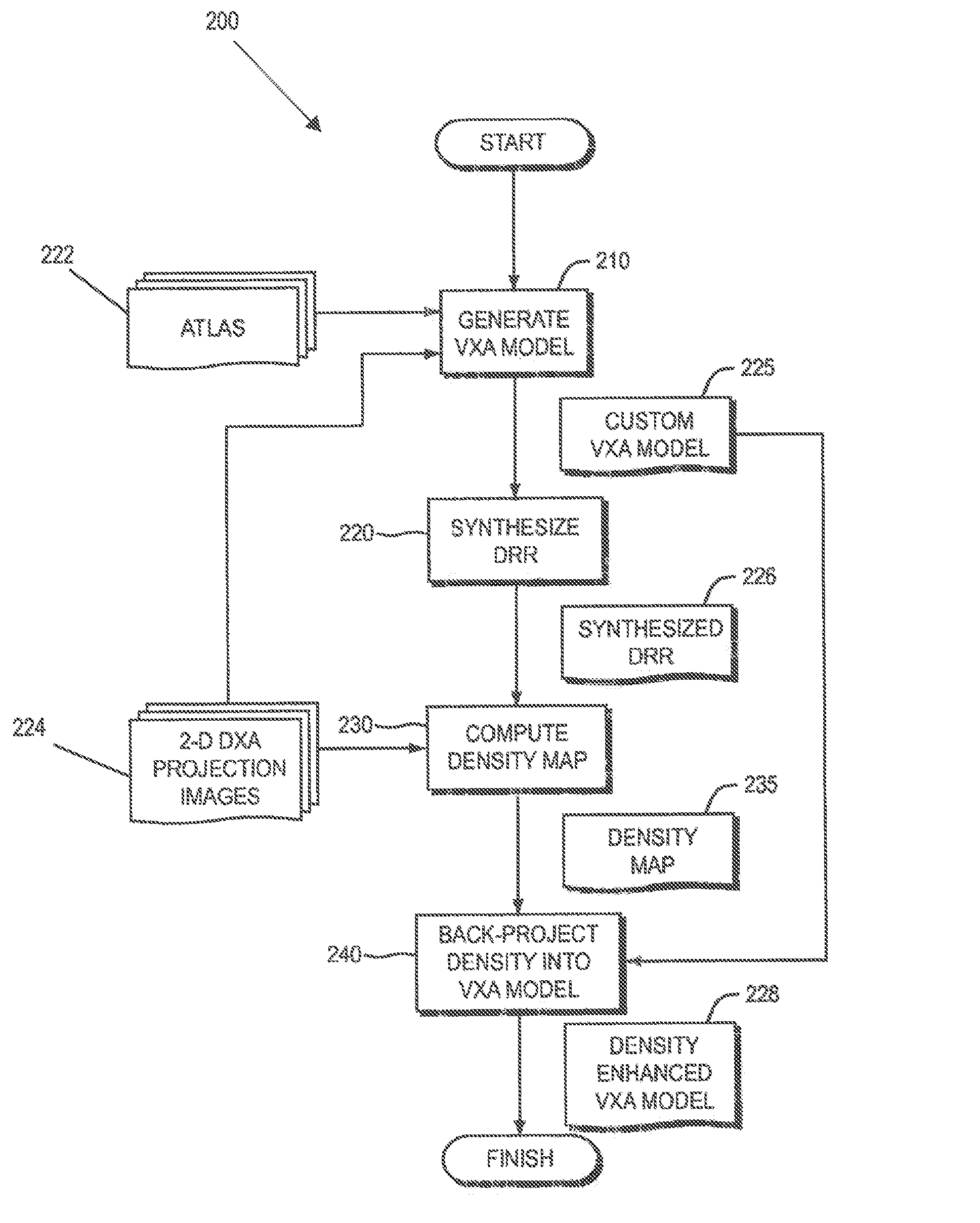
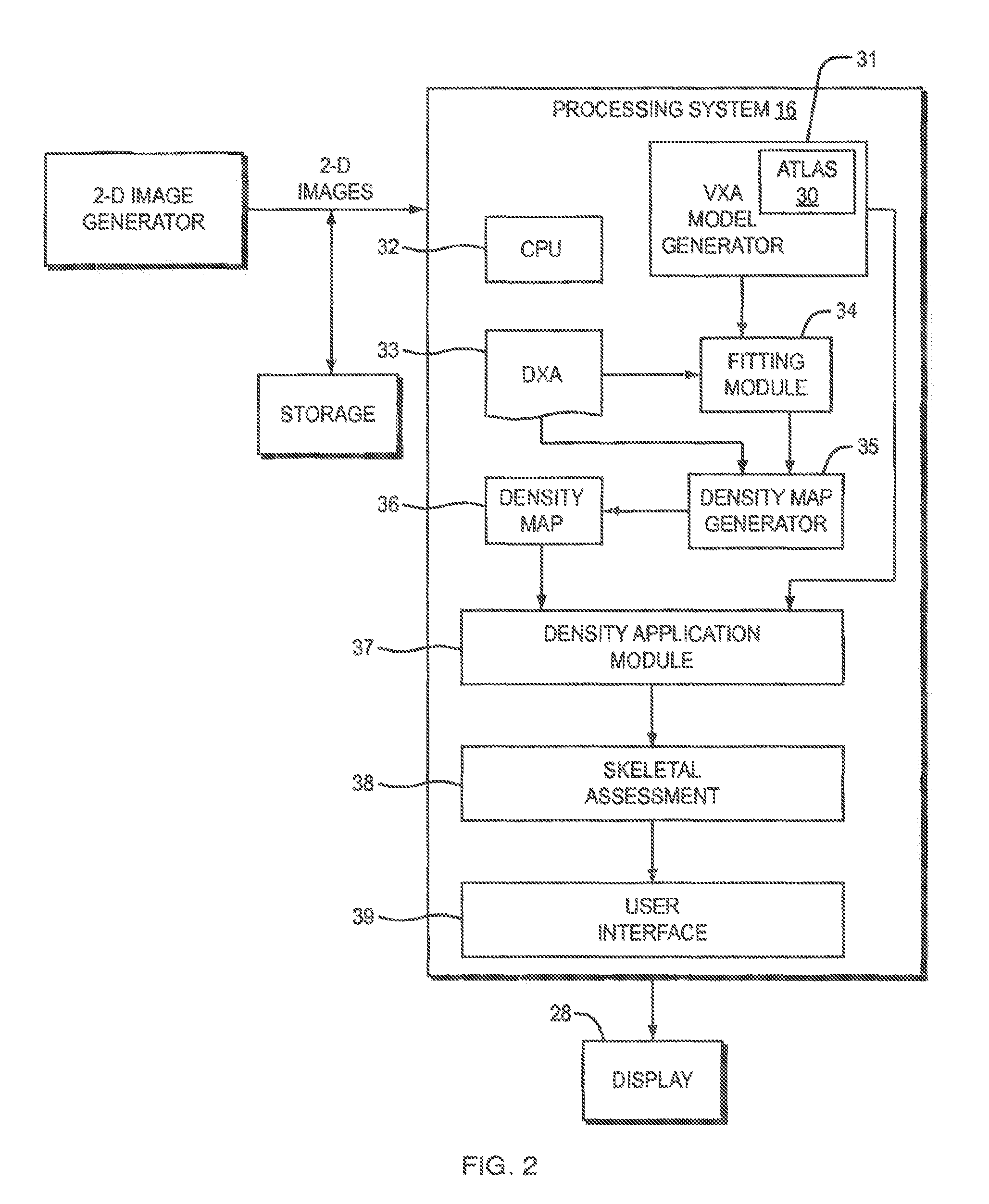
This patent describes a way to create a detailed model of an object by combining information from a pre-defined set of models and a single projection image. This model includes density information and can be used for skeletal assessment or displayed on a user interface. This method uses a density map that is calculated from a synthesized projection image and actual images of the structure, which results in similar spatial geometry and density results to QCT but with reduced patient exposure, equipment cost, and examination time.

Problems solved by technology

However one problem with DXA is that it fails to provide important 3-D information about the volumetric density and spatial geometry of imaged skeletal structures.
One issue with QCT lies in whether the quality of the information obtained by 3D structural evaluation using QCT outweighs the patient's increased exposure to radiation, the financial costs associated with QCT and the clinical feasibility of actual QCT practice.
However it has been determined that not all of the skeletal health assessment information provided by a customized VXA model meets the quality standards of QCT.
However, measurements which attempt to quantify the volumetric density of the skeletal structure, and in particular the Bone Mineral Density (BMD), have proven less reliable.

Method used


Image

  • System and method for generating enhanced density distribution in a three dimensional model of a structure for use in skeletal assessment using a limited number of two-dimensional views
  • System and method for generating enhanced density distribution in a three dimensional model of a structure for use in skeletal assessment using a limited number of two-dimensional views
  • System and method for generating enhanced density distribution in a three dimensional model of a structure for use in skeletal assessment using a limited number of two-dimensional views

Examples


Embodiment Construction

[0015]According to one aspect of the invention it is realized that a customized three-dimensional model of an imaged structure may be further transformed by applying one or more different gains to volume elements of the model to provide a density enhanced 3-D model of the imaged structure. Such a density-enhanced 3-D model of the image structure has been found to have spatial geometry and volumetric density information similar in quality to a QCT representation of the imaged structure. The gains that are applied to the volume elements of the 3-D model are determined by relating density information from projection images of the customized 3-D model to density information from one or more DXA images of the imaged structure. The present invention therefore provides improved skeletal assessment using 2-D images, thereby reducing patient exposure, procedure complexity and equipment cost.

[0016]Skeletal assessment using models of the present invention may be performed in a variety of envir...


PUM

PropertyMeasurementUnit
densityaaaaaaaaaa
bone mass densityaaaaaaaaaa
projection angleaaaaaaaaaa

Abstract

A method of generating a density enhanced model of an object is described. The method includes generating a customized a model of an object using a pre-defined set of models in combination with at least one projection image of the object, where the customized model is formed of a plurality of volume elements including density information. A density map is generated by relating a synthesized projection image of the customized model to an actual projection image of the object. Gains from the density map are back-projected into the customized model to provide a density enhanced customized model of the object. Because the density map is calculated using information from the synthesized projection image in combination with actual projection images of the structure, it has been shown to provide spatial geometry and volumetric density results comparable to those of QCT but with reduced patient exposure, equipment cost and examination time.

Description

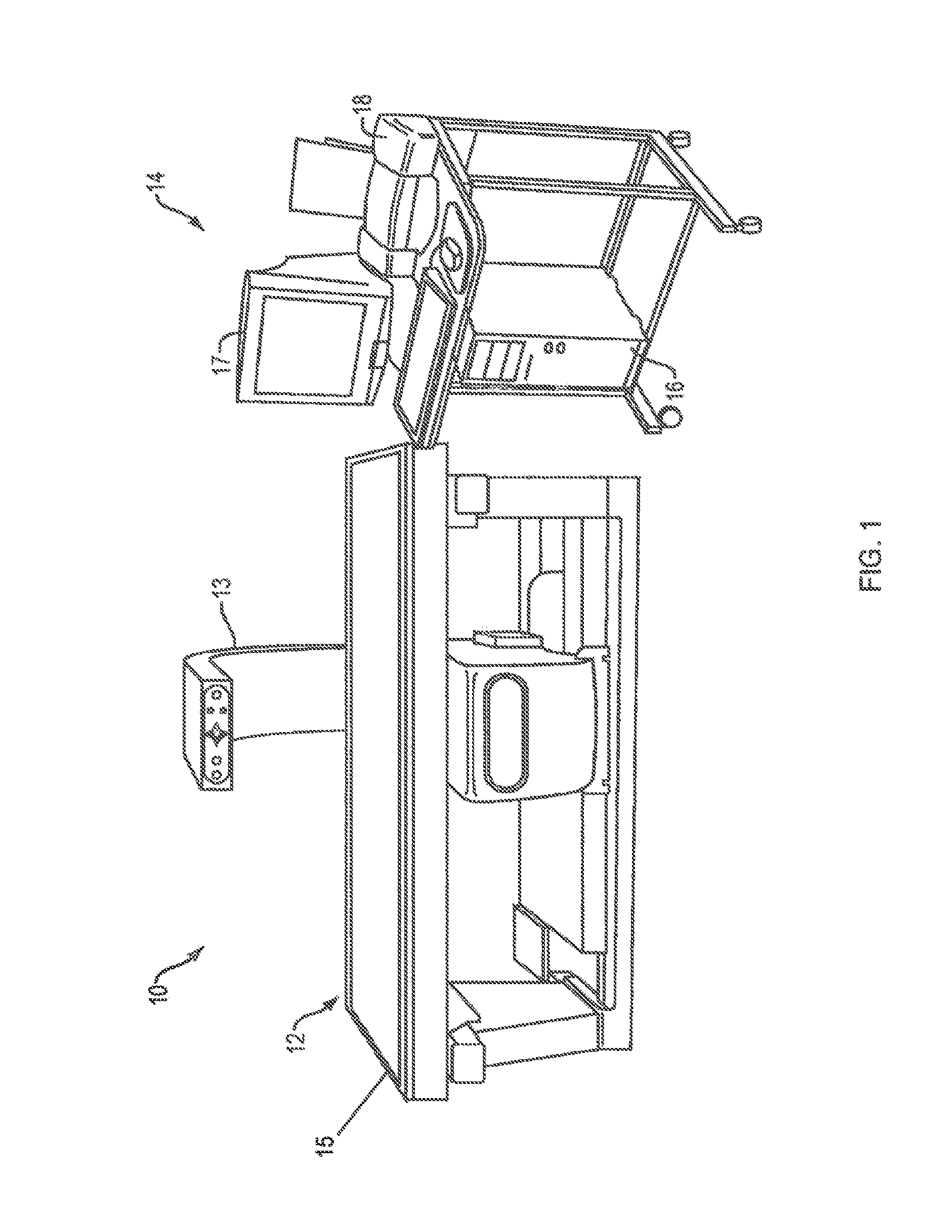
FIELD OF THE INVENTION[0001]The present invention relates generally to the field of skeletal assessment and more particularly to a system and method for generating enhanced density distributions in a 3-D model of a structure for use in skeletal assessment.BACKGROUND OF THE INVENTION[0002]Currently 2-D Dual-energy X-ray Absorptiometry is the gold standard of osteoporosis assessment. Dual-energy X-ray absorptiometry (DXA) is a means of performing skeletal assessment using x-ray beams of differing energy levels. A DXA system generally includes an examination table and a C-arm at opposite ends of which are mounted an x-ray tube and a multi-detector array. The patient is positioned on the examination table between the x-ray tube and the detector array of the C-arm and a fan-shaped beam of x-rays are directed from the tube to the detector as the tube and detector are scanned axially along the patient. The X-rays are alternatively pulsed at high and low energy ranges. By comparing the rela...

Claims


Application Information

Patent Timeline
Patent Type & Authority Patents(United States)
IPC IPC(8): G01N23/087
CPCG06T2210/41A61B6/505G06T19/20G06F19/3437A61B6/5247G06T11/006G06T2211/436G16H50/50
Inventor RAMAMURTHI, KRISHNAWILSON, KEVIN
Owner HOLOGIC INC
Learn More