
Control parameter adjustment in a discontinuous power mode

Active Publication Date: 2014-04-08
INFINEON TECH AMERICAS
View PDF5 Cites 13 Cited by
  • Summary
  • Abstract
  • Description
  • Claims
  • Application Information

AI Technical Summary

Benefits of technology

This patent is about a new way to control the voltage in a power supply. It explains that when the power supply is running at a high efficiency but not very frequently, the voltage needs to be adjusted to prevent the output voltage from dropping below a minimum acceptable level. The adjustment is made by changing the load-line resistance, which is the path through which the voltage is adjusted. This change in resistance changes the voltage needed to activate the control switch in the power supply. This technique helps to reduce the number of output capacitors needed in the power supply, which can save money and make it more efficient. The controller in the power supply uses a filter circuit to measure the current in real-time and adjust the load-line resistance accordingly. Overall, this patent introduces a new and innovative way to adjust the voltage in a power supply to ensure a stable output.

Problems solved by technology

Conventional applications such as those as discussed above can suffer from a number of deficiencies.
Conventional load-line voltage correction is currently not implemented during a discontinuous operational mode because the switching frequency of the power supply is typically too low during the discontinuous operational mode.
Producing a load-line voltage correction value based on the spike current through the inductor would result in a non-uniform load line voltage.
Accordingly, conventional techniques do not attempt to apply load-line voltage correction during a discontinuous operational mode.

Method used


Image

  • Control parameter adjustment in a discontinuous power mode
  • Control parameter adjustment in a discontinuous power mode
  • Control parameter adjustment in a discontinuous power mode

Examples


Embodiment Construction

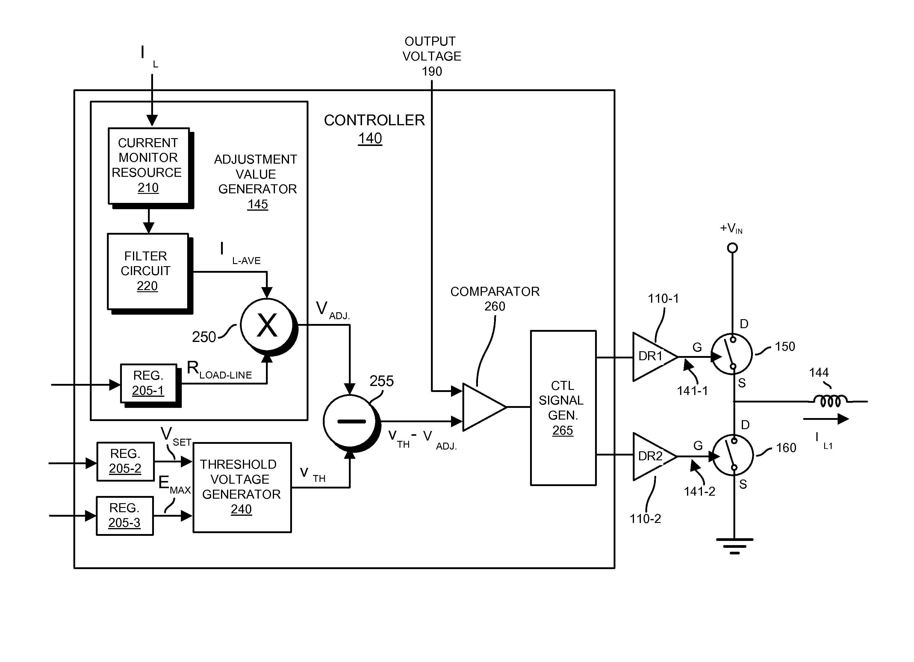
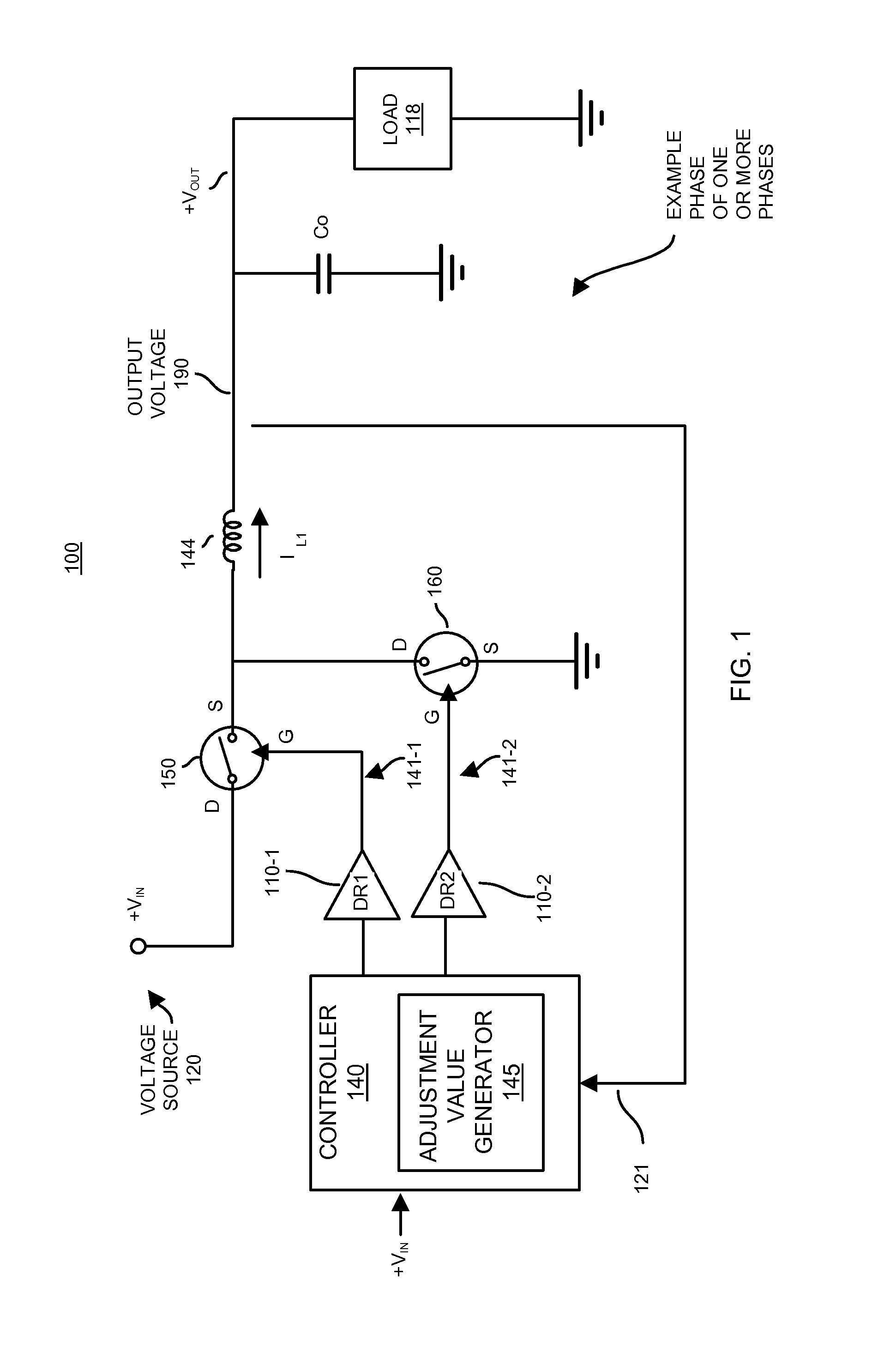
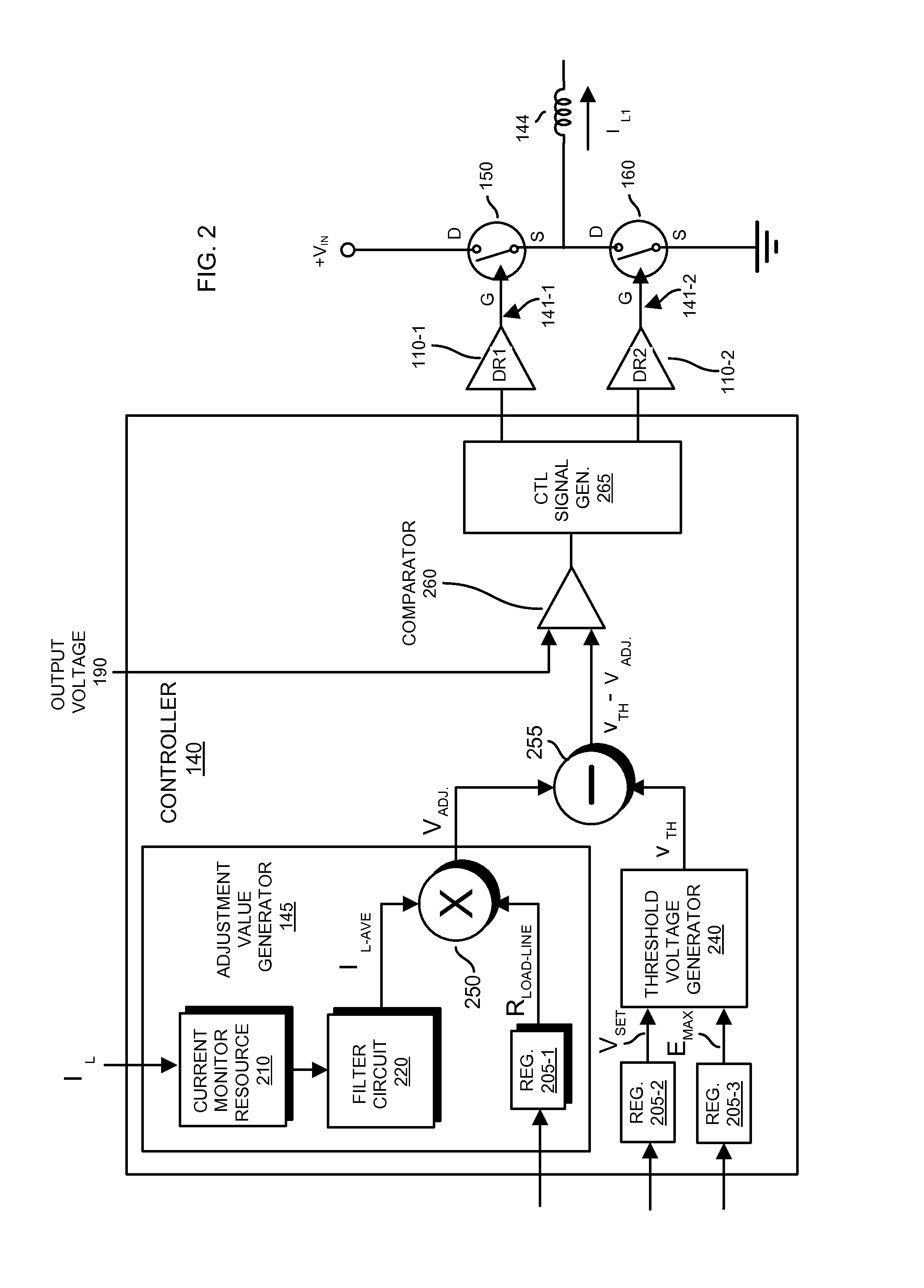
[0025]Embodiments herein include a unique and cost effective implementation of a discontinuous power supply mode in a switching power supply. For example, a controller can be configured to operate the power supply in a discontinuous mode. While in the discontinuous mode, a monitor resource in the controller monitors current supplied by one or more inductor resources in the power supply to produce an output voltage to power a load. An adjustment value generator produces an adjustment value based on a magnitude of the current supplied to the load by one or more inductor resources.

[0026]According to one configuration, the adjustment value equals the average inductor current (as supplied by the combination of one or more inductors) multiplied by the load-line resistance value of the power supply. The controller produces an adjusted trigger threshold value by reducing a trigger threshold value by the adjustment value generated by the adjustment value generator. The adjusted trigger thres...


PUM


Abstract

A controller operates a power supply in a discontinuous mode. While in the discontinuous mode, a monitor resource in the controller monitors current supplied by an inductor resource in the power supply to produce an output voltage to power a load. An adjustment value generator produces an adjustment value based on a magnitude of the current supplied to the load by the inductor resource. According to one configuration, the adjustment value equals the average inductor current multiplied by the load-line resistance value of the power supply. The controller produces an adjusted trigger threshold value by reducing a trigger threshold value by the adjustment value generated by the adjustment value generator. The adjusted trigger threshold value specifies a reduced threshold voltage at which the power supply controller turns ON a control switch in the power supply to increase an amount of current supplied by the inductor resource to the load.

Description

BACKGROUND[0001]Conventional switching power supply systems sometimes operate in a so-called discontinuous operational mode. Operation of a conventional switching power supply in the discontinuous mode can include three-state switching operation period cycle.[0002]For example, during a first switch state in the discontinuous mode switching cycle, the conventional power supply controller activates only a respective control switch to couple an inductor to a positive voltage source to increase an amount of current through the inductor to a load.[0003]During a second switch state in the discontinuous mode switching cycle, the conventional power supply controller deactivates the control switch and activates a synchronous switch to couple the inductor to ground. In general, activating the synchronous switch decreases the current supplied through the inductor to the load.[0004]During a third switch state in the discontinuous mode switching cycle, the conventional power supply controller de...

Claims


Application Information

Patent Timeline
IPC IPC(8): G05F1/00
CPCH02M3/156H02M2001/0025H02M2001/0009G05F1/00H02M1/0009H02M1/0025
Inventor SREENIVAS, VENKATCARROLL, ROBERT T.
Owner INFINEON TECH AMERICAS
Learn More