Imaging lens, imaging device and information device

a technology of imaging device and image, applied in the field of imaging device and information device, can solve the problems of insufficient correction of comatic aberration, distortion of chromatic aberration of magnification, and increasing the size of imaging device in view of portability, and achieve the effect of small aberration such as distortion

Inactive Publication Date: 2014-03-25
RICOH KK
View PDF18 Cites 4 Cited by
  • Summary
  • Abstract
  • Description
  • Claims
  • Application Information

AI Technical Summary

Benefits of technology

[0014]It is, therefore, an object of the present invention to provide a high-performance, small and bright imaging lens having two lens groups of positive and positive with a wide angle about 28 mm of 35 mm conversion and having a small aberration such as distortion, and a small and high-performance imaging device and an information device using such an imaging lens.

Problems solved by technology

Moreover, an imaging device has been increasingly downsized in view of its portability.
This retrofocus type lens which can keep an exit pupil position away from an imaging surface has a principal point back of the entire lens system, so that an asymmetry property is increased by a refractive power arrangement, and the correction of a comatic aberration, distortion and a chromatic aberration of magnification becomes insufficient.
The optical system described in Patent Document 4 also includes two positive lens groups, but the ratio of the imaging face to the entire length is large, so it is not sufficient for downsizing.
However, the optical system of Patent Document 1 has a long entire length, resulting in −3% distortion.
The optical system described in Patent Document 2 includes a small number of lenses, but its entire length is also long, so that the field curvature can not be sufficiently corrected.
However, the optical system described in Patent Document 3 includes about −10% distortion, which is insufficient for the correction of the aberration.
The optical system described in Patent Document 4 has a large ratio of the imaging face to the entire length, so that it can not be sufficiently downsized.

Method used


Image

  • Imaging lens, imaging device and information device
  • Imaging lens, imaging device and information device
  • Imaging lens, imaging device and information device

Examples


embodiment 1

[Embodiment 1]

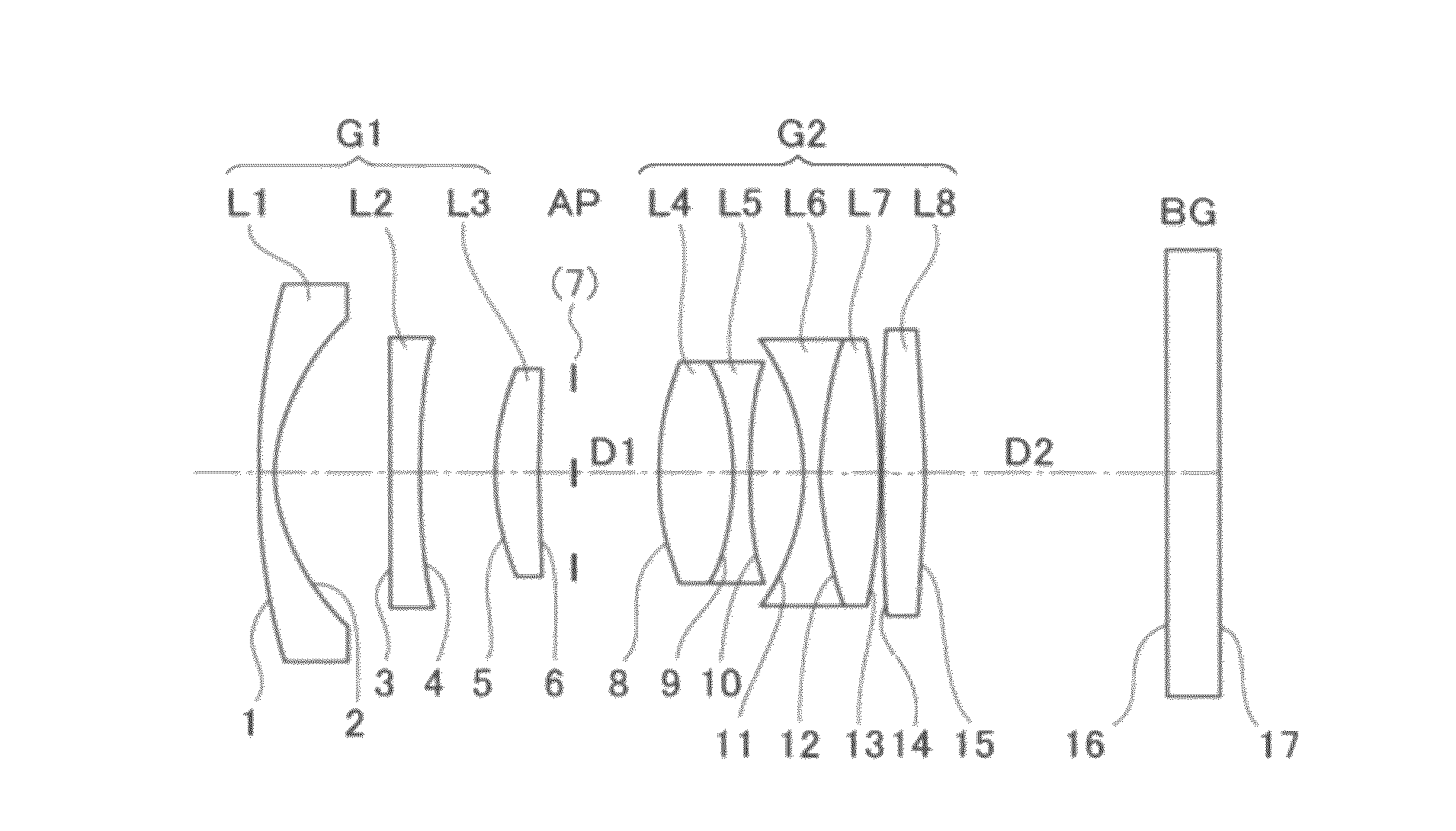
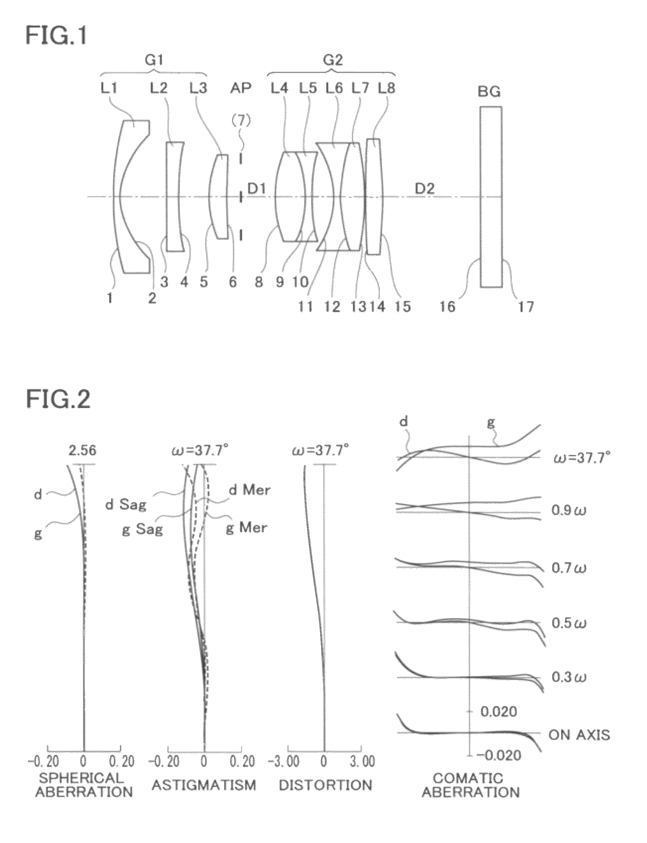
[0075]Next, specific embodiments (numerical embodiments) based on the above described embodiments will be described in details. The following Embodiments 1-7 are specific embodiments based on specific numerical embodiments of an imaging lens. The eighth embodiment is a specific embodiment of an imaging device or an information device using a lens unit including the imaging lens illustrated in Embodiments 1-7 as the optical system for imaging.

[0076]The aberrations of each imaging lens in Embodiments 1-7 are corrected at high level, and the spherical aberration, astigmatism, field curvature, and magnification chromatic aberration are sufficiently corrected. The distortion is 2.0% or below at an absolute value. By constituting an imaging lens as described in the following Embodiments 1-7, a preferable imaging performance can be ensured while having a wide angle about 38° of a half-field angle and a large diameter about 2.5 of F-number.

[0077]The meaning of signs which are ...

embodiment 2

[Embodiment 2]

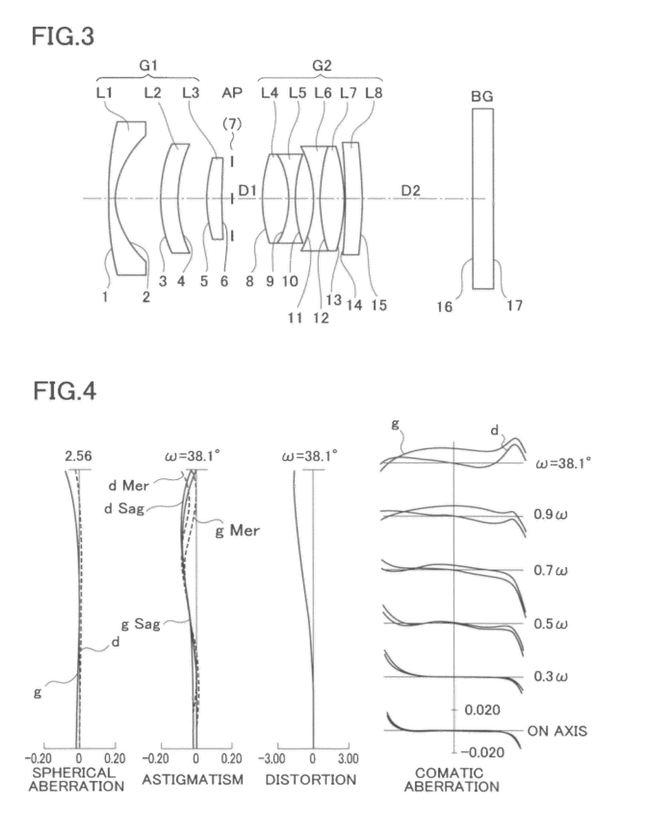
[0108]FIG. 3 provides a longitudinal sectional lens configuration in infinity focusing of an optical system of an imaging lens according to Embodiment 2.

[0109]The optical system of the imaging lens according to Embodiment 2 of the present invention includes in order from the object side to the image side a first lens L1, a second lens L2, a third lens L3, an optical aperture stop AP, a fourth lens L4, a fifth lens L5, a sixth lens L6, a seventh lens L7, an eighth lens L8, and a back insertion glass BG as illustrated in FIG. 3. This optical system includes six groups having eight lenses in which the fourth and fifth lenses L4, L5 constitute a cemented lens and the sixth and seventh lenses L6, L7 constitute a cemented lens. The surface numbers of the respective optical surfaces are illustrated in FIG. 3. As described above, the reference numbers in FIG. 3 are independently used with respect to each example; thus, even if the common reference numbers are used in FIGS. 1, ...

embodiment 3

[Embodiment 3]

[0127]FIG. 5 provides a longitudinal sectional lens configuration in infinity focusing of an optical system of an imaging lens according to Embodiment 3 of the present invention.

[0128]The optical system of the imaging lens according to Embodiment 3 of the present invention includes in order from the object side to the image side a first lens L1, a second lens L2, a third lens L3, a fourth lens L4, an aperture stop AP, a fifth lens L5, a sixth lens L6, a seventh lens L7, an eighth lens L8, a ninth lens L9 and a back insertion glass BG as illustrated in FIG. 5. This optical system includes six groups having nine lenses in which the third and fourth lenses L3, L4 constitute a cemented lens, the fifth and sixth lenses L5, L6 constitute a cemented lens and the seventh and eighth lenses L7, L8 constitute a cemented lens. The surface numbers of the respective optical surfaces are illustrated in FIG. 5. As described above, the reference numbers in FIG. 5 are independently used...


PUM


Abstract

An imaging lens includes an optical system having in order from an object side to an image side a first lens group having a positive refractive power and a second lens having a positive refractive power to image an optical image of an object, the first lens group and the second lens group being displaced in an extending amount different from one another to be focused on an object of a finite distance, the first lens group including a negative meniscus lens having a convex surface on the object side, a lens having a weak refractive power, and a lens having a positive refractive power, and the second lens group including four lenses or less or five lenses or less having at least one pair of a cemented lens.

Description

PRIORITY CLAIM[0001]The present application is based on and claims priority from Japanese Patent Application No. 2010-277550, filed on Dec. 13, 2010, the disclosure of which is hereby incorporated by reference in its entirety.BACKGROUND[0002]1. Technical Field[0003]The present invention relates to an improvement in a single focus imaging lens which is used as an imaging optical system in various camera including a silver salt camera, specifically, a digital camera, a video camera, a monitoring camera or the like, so as to image a subject image for imaging a still image or a moving image. The present invention also relates to an imaging lens suitable for an imaging device using an electronic imaging device such as a digital camera or a digital video camera, an imaging device such as a camera using such an imaging lens and an information device such as a personal digital assistant having an imaging function.[0004]2. Description of the Related Art[0005]In recent years, a digital still ...

Claims


Application Information

Patent Timeline
Patent Type & Authority Patents(United States)
IPC IPC(8): G02B9/06
CPCG02B13/0045G02B9/62
Inventor KUBOTA, TAKASHI
Owner RICOH KK
Why Eureka
Try Eureka