Electrophoretic display panel
a display panel and electrophoretic technology, applied in the field of electrophoretic display panels, can solve the problems of difficult arrangement of electrodes and interconnection lines
- Summary
- Abstract
- Description
- Claims
- Application Information
AI Technical Summary
Benefits of technology
Problems solved by technology
Method used
Image
Examples
first embodiment
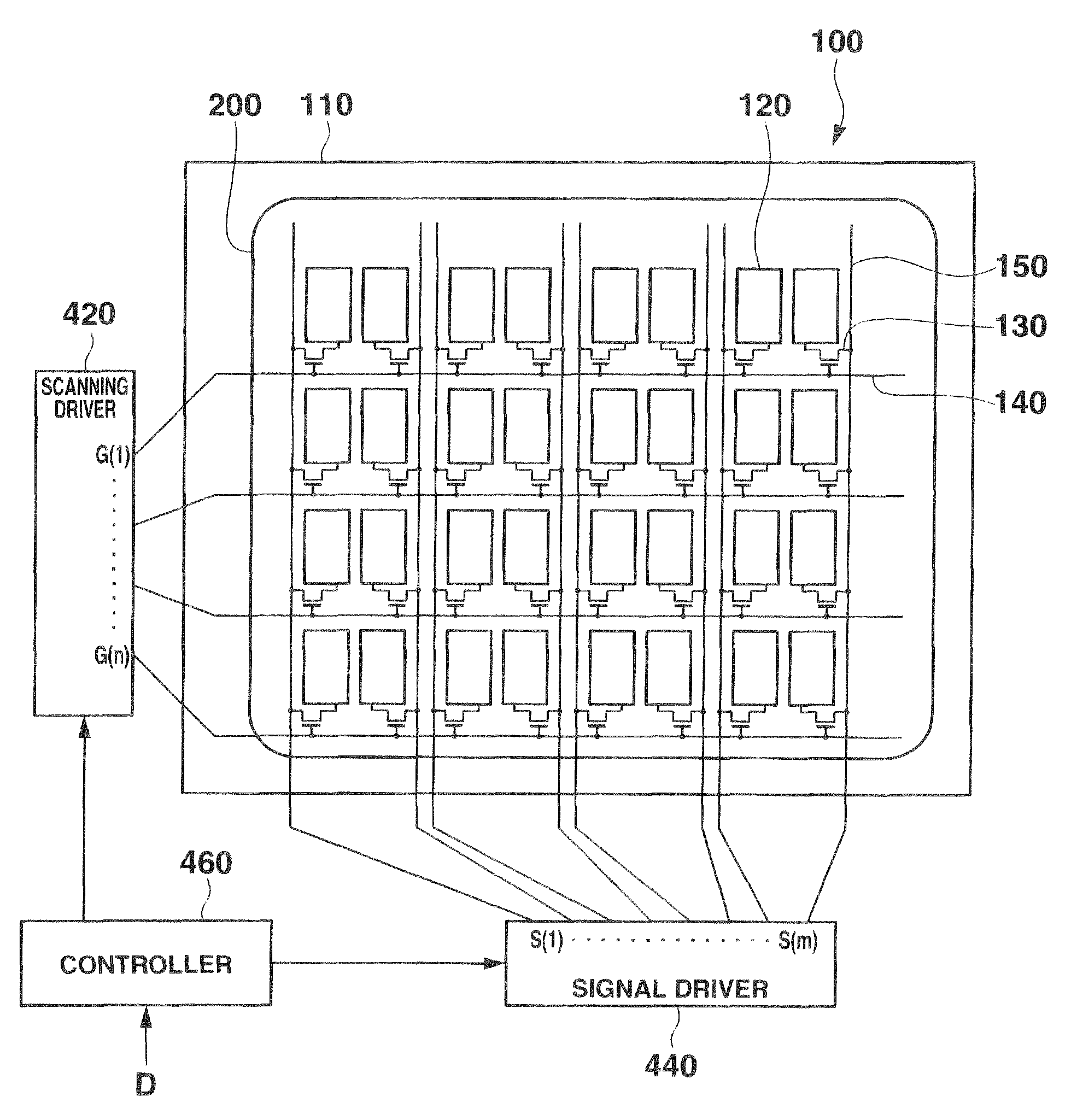
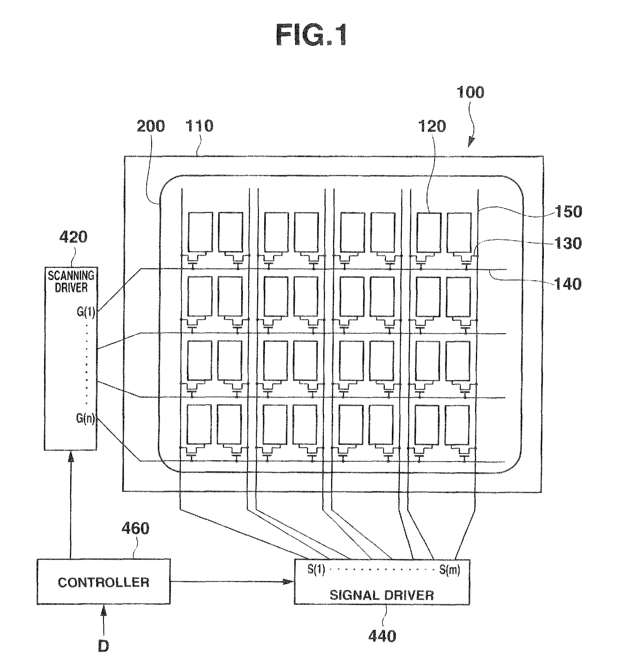
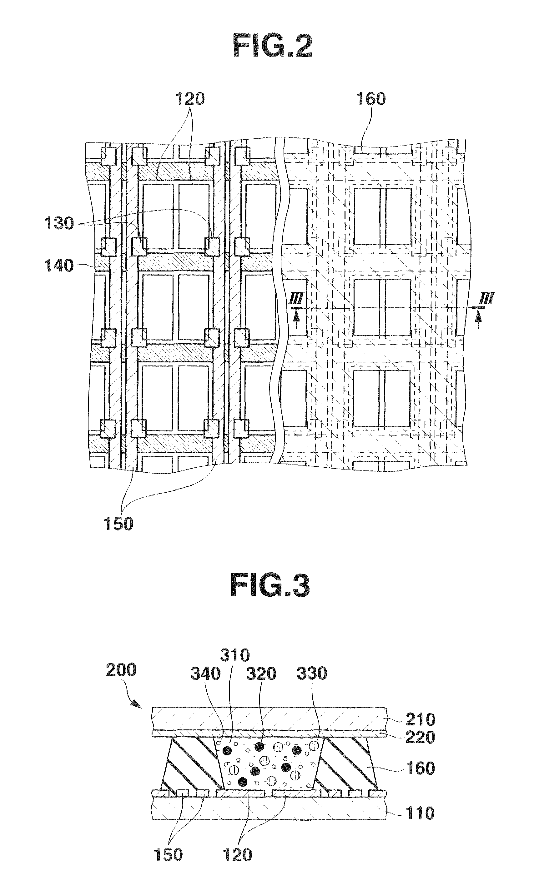
[0027]The first embodiment of the present invention will be described first with reference to the accompanying figures. FIG. 1 is a view showing the arrangement of a display apparatus including an electrophoretic display panel according to the embodiment. As shown in FIG. 1, the electrophoretic display apparatus includes a display panel 100, a scanning driver 420, a signal driver 440, and a controller 460. The display panel 100 displays an image based on image data D supplied out of the electrophoretic display apparatus. The display panel 100 includes a display device having an electrophoretic layer sandwiched between a pixel-side substrate 110 and a COM substrate 200.
[0028]A plurality scanning lines 140 (G(j) (j=1, 2, . . . , n)) and a plurality of signal lines 150 (S(i) (i=1, 2, . . . , m)) run so as to intersect each other on the pixel-side substrate 110. A pixel electrode 120 is arranged at each of positions corresponding to the intersections between the scanning lines 140 and t...
second embodiment
[0047]The second embodiment of the present invention will be described low with reference to the accompanying figures. Only the differences from the first embodiment will be described here. In the first embodiment, the pixel electrode 120 has a rectangular shape with one corner cut away, and two pixel electrodes are arranged per pixel to be line-symmetrical, as shown in FIG. 10. In the first embodiment, when one pixel electrode 120 in one pixel is set at a positive voltage, and the other pixel electrode 120 is set at a negative voltage for white display, the positively-charged black particles 320 and the negatively-charged red particles 330 gather on the negative electrode and the positive electrode, respectively. When the shield of the neutral white particles 340 is sufficient, the observer cannot view the state in which the positively-charged black particles 320 and the negatively-charged red particles 330 gather on the corresponding electrodes and are thus separated into two. Con...
third embodiment
[0051]The third embodiment of the present invention will be described below with reference to the accompanying figures. Only the differences from the first embodiment and the second embodiment will be described here as well. In the first embodiment and the second embodiment, the adjacent and opposite sides of the two pixel electrodes 120 in one pixel are linear. The scanning lines, signal line, and capacity lines are linear, too. For this reason, when the shield of the neutral white particles 340 is insufficient, the adjacent and opposite sides of the two pixel electrodes 120 in one pixel may interfere with the scanning lines, the signal line, and the capacity lines. As a result, interference fringes will be generated. The interference fringes may generate noise that deteriorates the display quality of the electrophoretic display panel. To prevent this, in the third embodiment, the adjacent and opposite sides of two pixel electrodes 120 in one pixel are curved.
[0052]FIG. 14 shows an...
PUM
| Property | Measurement | Unit |
|---|---|---|
| areas | aaaaa | aaaaa |
| reflectivity | aaaaa | aaaaa |
| flexible | aaaaa | aaaaa |
Abstract
Description
Claims
Application Information
 - R&D
- Intellectual Property
- Life Sciences
- Materials
- Tech Scout
- Unparalleled Data Quality
- Higher Quality Content
- 60% Fewer Hallucinations
Browse by: Latest US Patents, China's latest patents, Technical Efficacy Thesaurus, Application Domain, Technology Topic, Popular Technical Reports.
© 2025 PatSnap. All rights reserved.Legal|Privacy policy|Modern Slavery Act Transparency Statement|Sitemap|About US| Contact US: help@patsnap.com


