
High speed data cable with impedance correction

a high-speed data cable and impedance correction technology, applied in the direction of electrically conductive connections, transmission, conductors, etc., can solve the problems of high manufacturing and termination costs, and achieve the effect of superior properties

Active Publication Date: 2014-03-18
REDMERE TECH
View PDF18 Cites 17 Cited by
  • Summary
  • Abstract
  • Description
  • Claims
  • Application Information

AI Technical Summary

Benefits of technology

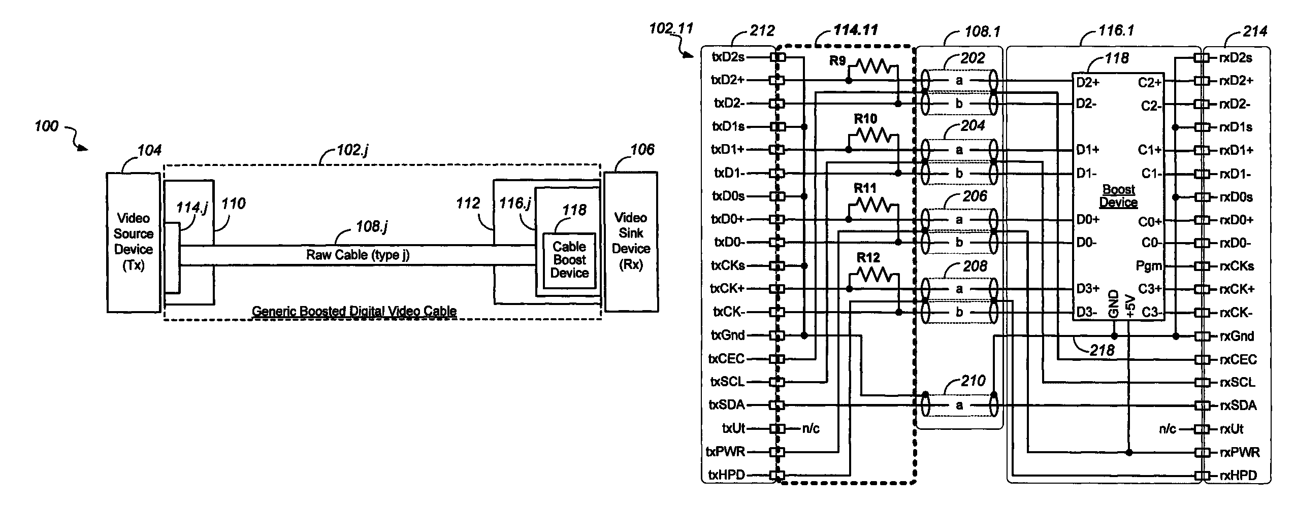
The invention provides an improved boosted high speed data cable with impedance correction for transmitting high speed differential digital data signals and auxiliary signals between a source device and a sink device. The cable includes a raw cable with dual shielded cable elements that have an impedance higher than the cable specification. A first circuit carrier connects the source device to the raw cable and includes a shunt resistor in parallel with the shielded conductors of the cable. A second circuit carrier connects the source device to the boost device. The boost device includes an equalizer and amplifier for equalizing and boosting the signals. The cable design meets the HDMI or DisplayPort standard and can be used for high-speed data transmission.

Problems solved by technology

The resulting complex cable configuration with numerous wires, some of which are individually shielded, is expensive to manufacture and terminate.

Method used


Image

  • High speed data cable with impedance correction
  • High speed data cable with impedance correction
  • High speed data cable with impedance correction

Examples


Embodiment Construction

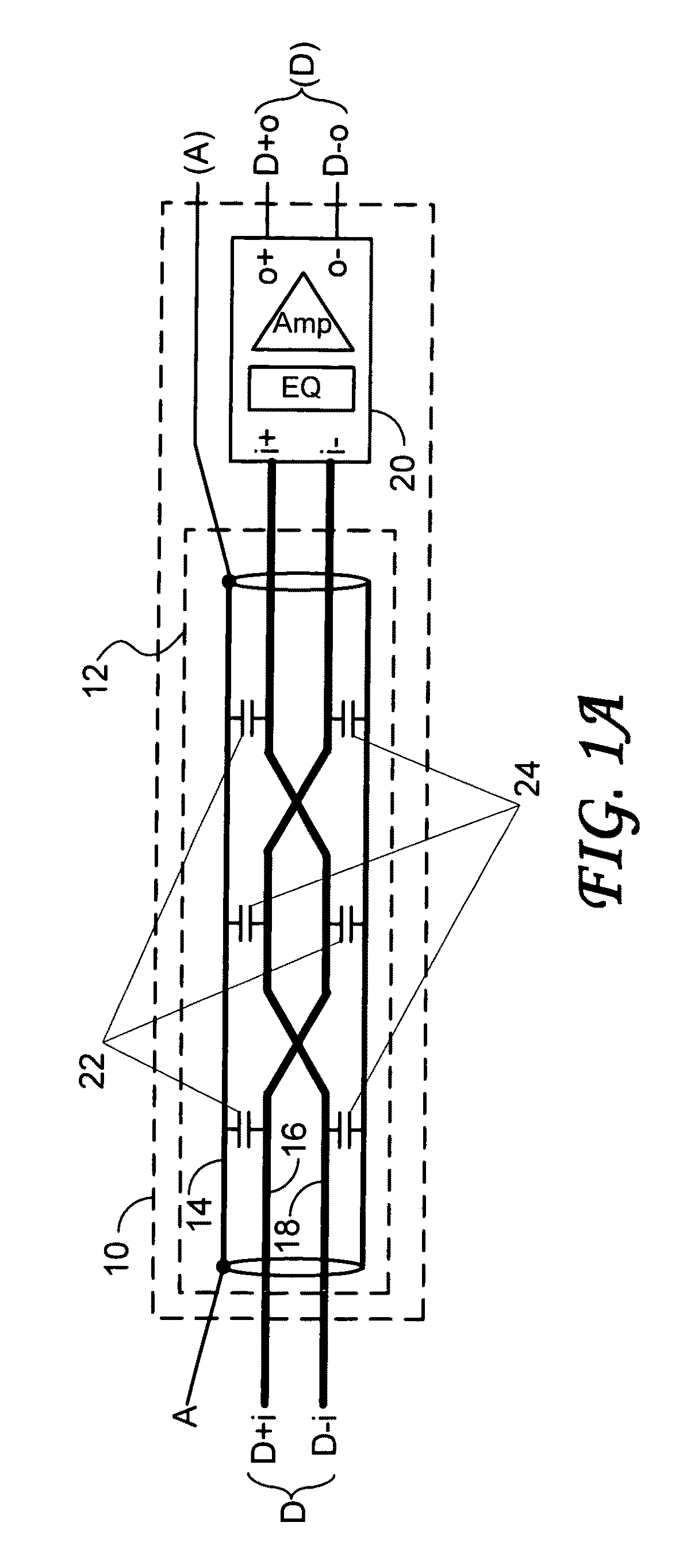
[0072]Embodiments of the present invention describe a boosted high speed cable comprising shielded high speed signal lines and carrying other signals of lower speed as well as power and ground, in which the shields of the shielded high speed signal lines are used in carrying the lower speed signals and power and ground.

[0073]The inherent characteristics and manufacturing imperfections of high-speed differential signaling cables such as may be used to carry HDMI signals have an adverse effect on the high-speed signals carried by the cable. To mitigate these effects, various boosted high speed data cables have been proposed by the industry. For example, in the previously filed US application of the same assignee, Ser. No. 11 / 826,713 filed on Jul. 18, 2007, a boost device is embedded in the cable, the entire contents of the patent application being incorporated herein by reference.

[0074]The inventors have discovered that the boost device may not only be used to equalize and boost the s...


PUM

PropertyMeasurementUnit
impedancesaaaaaaaaaa
impedanceaaaaaaaaaa

Abstract

A high speed video cable carries signals according to the High-Definition Multimedia Interface (HDMI) or DisplayPort standards, and includes a raw cable and may include a boost device. The raw cable includes coaxial lines of a characteristic cable impedance higher than the impedance implied in the standards. The correct impedance is observed at the sending end by shunt resistors mounted in the first cable connector. The resultant loss of signal may be made up with the boost device mounted in the connector at the other end of the cable in the case of a long cable.

Description

CROSS REFERENCE TO RELATED APPLICATIONS[0001]This application is Continuation-in-Part of the U.S. application Ser. No. 12 / 805,101 filed on Jul. 13, 2010, the entire contents of which are incorporated herein by reference.FIELD OF THE INVENTION[0002]The present invention relates to the construction of high speed data cables, which may or may not be boosted, and carry high speed signal lines.BACKGROUND OF THE INVENTION[0003]The distribution of television signals has increasingly become based on digital methods and digitally encoded forms of video and audio signals. At the same time, higher resolution (high definition TV) has become available in the market place, commensurate with larger and higher definition displays. To meet the requirement of interconnecting such high definition displays with digital signal sources such as Digital Versatile Disc (DVD) players and receivers / decoders for digital satellite and digital cable distribution of video material, a digital interface standard ha...

Claims


Application Information

Patent Timeline
Patent Type & Authority Patents(United States)
IPC IPC(8): H01B7/00
CPCH04B3/02H04L25/0278H01B11/18H04L25/03878H04L25/0272
Inventor HORAN, JOHN MARTINMURPHY, GERALD DONALMCGOWAN, DAVID WILLIAM
Owner REDMERE TECH
Learn More