
Method and apparatus for predicting work of breathing

a breathing and work technology, applied in the field of respiratory therapy and physiology, can solve the problems of affecting the breathing of patients with weakened bodies, and being beyond the capacity or capability of small or disabled patients, and achieve the effect of avoiding respiratory muscle fatigue and respiratory muscle deconditioning

Inactive Publication Date: 2014-03-18
UNIV OF FLORIDA RES FOUNDATION INC
View PDF31 Cites 10 Cited by
  • Summary
  • Abstract
  • Description
  • Claims
  • Application Information

AI Technical Summary

Benefits of technology

Enables noninvasive and accurate prediction of patient effort, facilitating optimal ventilatory support that minimizes muscle fatigue and improves extubation success by simulating natural breathing patterns.

Problems solved by technology

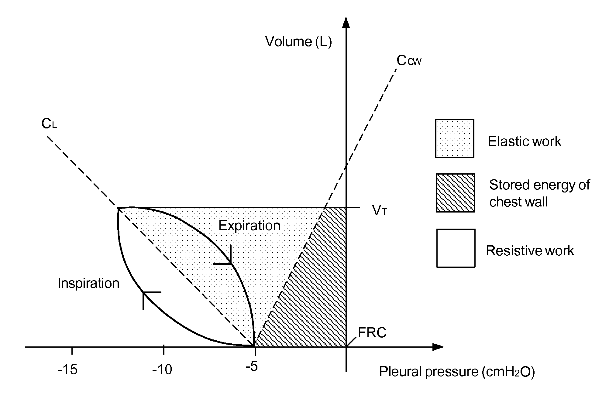
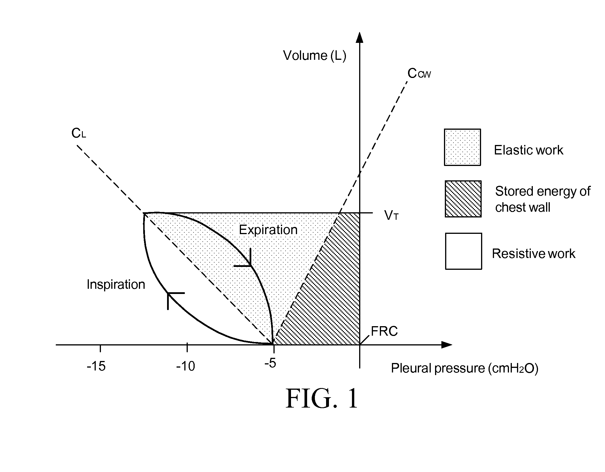
It is desirable to reduce the effort expended by the patient in each of these phases, because a high total work of breathing load can cause further damage to a weakened patient or be beyond the capacity or capability of small or disabled patients.
High work loads tend to create breathing patterns that are rapid and shallow (high frequency and low tidal volume).
Since that time, mechanical ventilators have become more sophisticated and complicated in response to increasing understanding of lung pathophysiology.
The prior art microprocessor controlled ventilators suffered from compromised accuracy due to the placement of the sensors required to transduce the data signals.
Consequently, complicated algorithms were developed so that the ventilators could “approximate” what was actually occurring within the patient's lungs on a breath-by-breath basis.
In effect, the computer controlled prior art ventilators were limited to the precise, and unyielding, nature of the mathematical algorithms that attempted to mimic cause-and-effect in the ventilator support provided to the patient.
The physiological determinants, which include the nature of the pulmonary disease, the ventilatory efforts of the patient, and many other physiological variables, changes with time and are difficult to diagnose.
Moreover, the physician historically had relatively little control over these determinants.
Insufficient ventilatory support places unnecessary demands upon the patient's already compromised respiratory system, thereby inducing or increasing respiratory muscle fatigue.
Excessive ventilatory support places the patient at risk for pulmonary-barotrauma, respiratory muscle deconditioning, and other complications of mechanical ventilation.
Although total work of breathing (and its alternatives) has been considered an important parameter for appropriately setting a ventilator, it has remained largely unused because of the difficulty in obtaining its value.
Likewise, although imposed work of breathing has been considered an important parameter for appropriately setting a ventilator, it has also remained largely unused because of the difficulty in obtaining its value.
The greatest single difficulty with these devices is the harsh environment in which they exist and their propensity for becoming clogged.
For this and other reasons, tracheal pressure is difficult to reliably measure and thus is not normally used.
A problem with the method taught by the '009 patent is that Pmus is difficult to measure in a spontaneously breathing patient because the parameters R and C must be very accurately computed in order for Pmus to correlate with “work”.
Moreover, R and C in a spontaneously breathing patient with ventilator support are very difficult to obtain accurately.

Method used


Image

  • Method and apparatus for predicting work of breathing
  • Method and apparatus for predicting work of breathing
  • Method and apparatus for predicting work of breathing

Examples


example 1

Prediction of Power of Breathing

[0061]With one particular subset of parameters (respiratory system resistance, compliance, tidal volume, and frequency), the present invention predicted power of breathing with a correlation coefficient well over 0.90. Similar results were obtained with other combinations of parameters. FIG. 3 shows a plot of predicted versus actual, or measured, power of breathing. A perfect prediction would be indicated by all values having identical x- and y-axis values, and thus would fall on the diagonal black line 40 shown in the FIG. 3. The wider the spread from this line, the lower the correlation between predicted and actual power of breathing. In this particular prediction, data was obtained from 150 patients collected at Shands Hospital at the University of Florida. The data was collected with multiple ventilator settings for each patient, thus giving us approximately 500 data points in the study.

example 2

Data for a Prediction (Table 1 Includes the First Data Points)

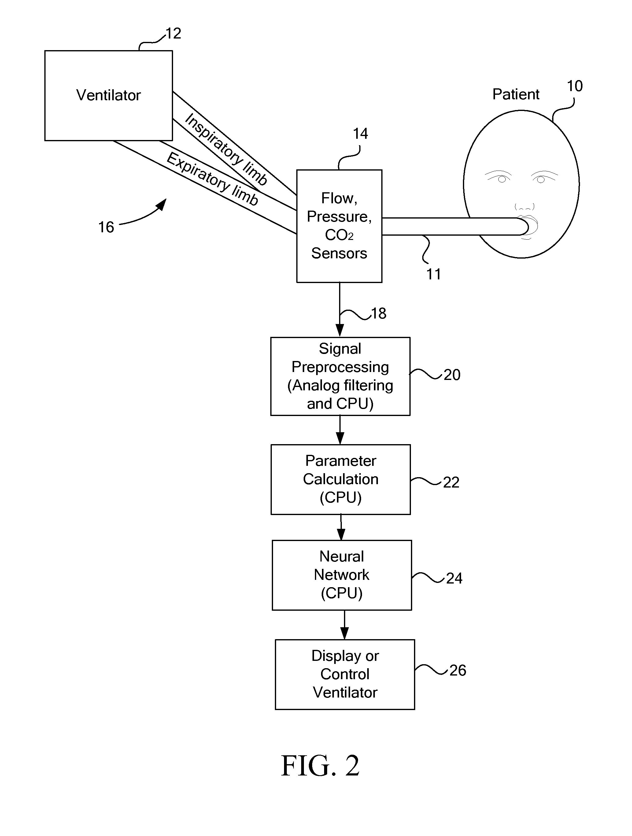
[0062]During data collection, respiratory measurements are made continuously and collected. These measurements are stored and later fed to the neural network for training. After the neural network model is trained successfully, the measurements from future are input to the “trained” model to produce a noninvasive prediction of actual power of breathing. This prediction of power of breathing is then used in a downstream fuzzy logic system that recommends changes to the ventilator.

[0063]In this example, the inputs / outputs to the system are:[0064]Minute Ventilation—the total volume delivered to the patient per minute (e.g. roughly tidal volume times breath frequency) in Liters.[0065]Trigger Gradient—the slope of the airway pressure drop due to the patient effort that riggers the breath (e.g. before the ventilator starts providing flow to the patient) in cm H2O per second.[0066]Pressure Rise Time—the time it takes for the flo...


PUM


Abstract

A method of creating a noninvasive predictor of both physiologic and imposed patient effort of breathing from airway pressure and flow sensors attached to the patient using an adaptive mathematical model. The patient effort is commonly measured via work of breathing, power of breathing, or pressure-time product of esophageal pressure and is important for properly adjusting ventilatory support for spontaneously breathing patients. The method of calculating this noninvasive predictor is based on linear or non-linear calculations using multiple parameters derived from the above-mentioned sensors.

Description

CROSS REFERENCE TO RELATED APPLICATIONS[0001]This application is a continuation-in-part application of Ser. No. 12 / 499,576, filed Jul. 8, 2009; which is a continuation application of U.S. Ser. No. 11 / 758,159, filed Jun. 5, 2007, now U.S. Pat. No. 7,588,543; which is a continuation application of U.S. Ser. No. 10 / 652,992, filed Aug. 29, 2003, now U.S. Pat. No. 7,425,201; which claims the benefit of U.S. Provisional Application Ser. No. 60 / 407,099, filed Aug. 30, 2002, each of which is hereby incorporated by reference herein in its entirety.FIELD OF THE INVENTION[0002]The present invention relates generally to the field of respiratory therapy and physiology, including ventilator and respiratory monitor technology, and, more particularly, to a method and apparatus for predicting a patient's physiologic work of breathing and imposed work of breathing.BACKGROUND[0003]Mechanical ventilatory support is widely accepted as an effective form of therapy and means for treating patients with res...

Claims


Application Information

Patent Timeline
Patent Type & Authority Patents(United States)
IPC IPC(8): A61B5/02
CPCA61M16/00A61M2230/432A61B5/087A61M2016/0036A61M2016/0021A61M2205/15A61M2230/205A61M16/0051A61M2016/0027A61B5/085A61B5/0836A61M2016/103A61B5/037A61M2230/46A61M16/026
Inventor EULIANO, NEIL R.BRENNAN, VICTOR L.BLANCH, PAUL B.BANNER, MICHAEL J.
Owner UNIV OF FLORIDA RES FOUNDATION INC
Learn More