Arthroscopic surgery assisting device for orthopedics department
A technology of arthroscopic surgery and auxiliary devices, applied in surgery, operating tables, medical science, etc., can solve problems such as soreness in lower limbs, affect the effect of surgery, and discomfort in the back, so as to increase comfort, increase diversity, and improve stability Effect
- Summary
- Abstract
- Description
- Claims
- Application Information
AI Technical Summary
Problems solved by technology
Method used
Image
Examples
Embodiment 1
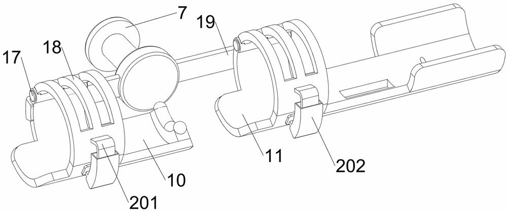
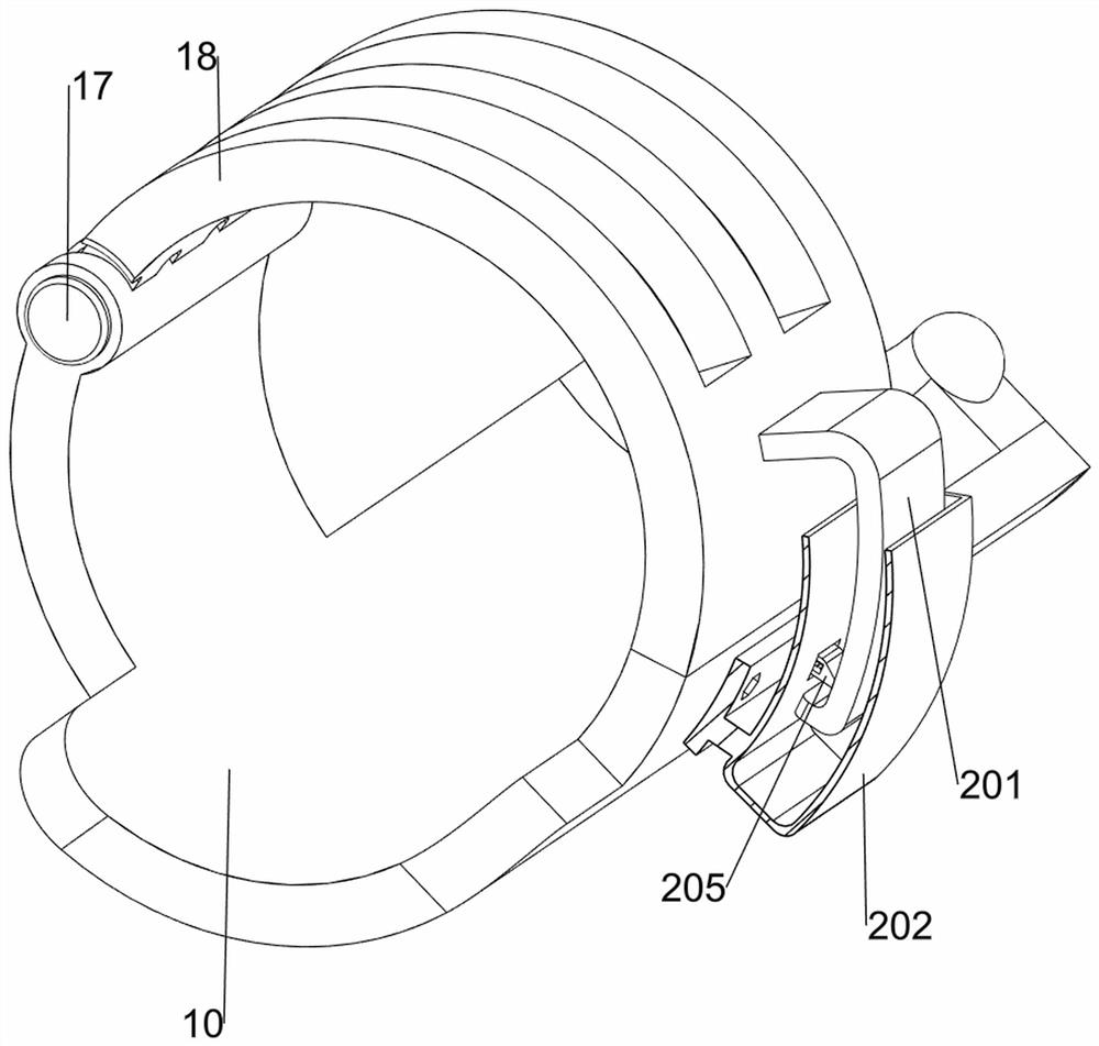
[0043] An auxiliary device for orthopedic arthroscopic surgery, such as Figure 1-12 As shown, it includes a bed frame 1, a bed board 2, a back pad 3, a head pad 4, a handle 5, a first support plate 6, a sliding shaft 7, a connecting shaft 8, a first connecting block 9, a first fixing frame 10, The second fixing frame 11, the first connecting frame 12, the sliding block 13, the first guide rod 14, the second connecting frame 15, the connecting plate 16, the first rotating shaft 17, the rotating cover 18, the second connecting block 19, the buckle mechanism 20. The adjustment mechanism 21 and the lifting mechanism 22, the upper side of the bed frame 1 is welded and connected with the bed plate 2, the material of the bed frame 1 is aluminum alloy, the weight is light, and the strength is relatively hard, and the upper side of the left part of the bed frame 2 is connected with a back pad by bolts 3. The head pad 4 is installed on the upper side of the left part of the back cushio...
Embodiment 2
[0049] On the basis of Example 1, as figure 1 and Figure 12 As shown, it also includes a clamping mechanism 23, the clamping mechanism 23 includes a fourth connection block 231, a clamping tooth 232, a fourth guide rod 233 and a third spring 234, and a fourth connection is welded on the upper right side of the foot pad 214. Block 231, the right part of the second fixing frame 11 is slidably provided with two fourth guide rods 233, the upper parts of the two fourth guide rods 233 are bolted and connected with the locking teeth 232, and the fourth connecting block 231 is in contact with the locking teeth 232 , a third spring 234 is connected between the tooth 232 and the second fixing frame 11 , and the third spring 234 is wound around the outer side of the fourth guide rod 233 .
[0050] The foot of the patient steps on the upper foot pad 214. If the patient's leg is long, the foot pad 214 is pushed to the right, the second spring 213 enters the stretched state, and the foot ...
Embodiment 3
[0052] On the basis of Example 2, as figure 1 and Figure 13 As shown, a tripping mechanism 24 is also included. The tripping mechanism 24 includes a pulling rope 241, a threading shaft 242, a fourth support plate 243, a rotating rod 244, a roller 245, a torsion spring 246, a spur gear 247, and a second rotating shaft 248. A threading shaft 242 and a fourth support plate 243 are symmetrically arranged on the side separated from the right part of the two second fixing frames 11 and the sector gear 249 , and the threading shaft 242 penetrates through the second fixing frame 11 and the fourth supporting plate 243 The upper rotating type is provided with a rotating rod 244, a roller 245 is sleeved on the rotating rod 244, a pulling rope 241 is connected to the lower side of the roller 245, and the stretching end is connected with the lower side of the clamping tooth 232 through the threading shaft 242, and the left end of the rotating rod 244 passes through A spur gear 247 is con...
PUM
 Abstract
Description
Claims
Application Information
 - R&D
- Intellectual Property
- Life Sciences
- Materials
- Tech Scout
- Unparalleled Data Quality
- Higher Quality Content
- 60% Fewer Hallucinations
Browse by: Latest US Patents, China's latest patents, Technical Efficacy Thesaurus, Application Domain, Technology Topic, Popular Technical Reports.
© 2025 PatSnap. All rights reserved.Legal|Privacy policy|Modern Slavery Act Transparency Statement|Sitemap|About US| Contact US: help@patsnap.com


